I would like to support greedy Papa Jr too.
Yep, very nice, but i prefer threadjacking

http://www.datasheet4u.com/download.php?id=254740
Doe's anyone have a suggestion to a matching setup for thoose j309 ??? Or should i just use same value's as i do when matching 2sk170bl ???
lykkedk said:
.........
Doe's anyone have a suggestion to a matching setup for thoose j309 ??? Or should i just use same value's as i do when matching 2sk170bl ???
yup............. make ccs for 8mA ,then measure Uds
Thank you ZenMod for helping me out... I will never ask quistion that i allready know, but it's in my nature to ask, instead of be in doubt ")
Then when voltagedrop between GND and +out , GND -out are just the same, the pumpkin will have perfect match between +/- out ? I do not have to meassure voltagedrop on thoose resistors rihgt ???
You mentioned that the uses ~50mA each channel will that be 72v / 0,05 = 3,6Watt(1channel) = allmost nothing ??? then there will be need for small heatsinks only, as i see.
Ok.. I will soon be ready to fire 1. channel up, are there any other thing's to consider ?
Jesper.
Btw: My problem with the bosoz 36-/36+ psu was 2shorted zener's !
with WR2 you can adjust currents through left and right output CCS-es (look at currents through R7 and R8) and - accordingly - offset between outputs AND GND
Then when voltagedrop between GND and +out , GND -out are just the same, the pumpkin will have perfect match between +/- out ? I do not have to meassure voltagedrop on thoose resistors rihgt ???
You mentioned that the
uses ~50mA each channel will that be 72v / 0,05 = 3,6Watt(1channel) = allmost nothing ??? then there will be need for small heatsinks only, as i see.Ok.. I will soon be ready to fire 1. channel up, are there any other thing's to consider ?
Jesper.
Btw: My problem with the bosoz 36-/36+ psu was 2shorted zener's !
lykkedk said:Thank you ZenMod for helping me out... I will never ask quistion that i allready know, but it's in my nature to ask, instead of be in doubt
Then when voltagedrop between GND and +out , GND -out are just the same, the pumpkin will have perfect match between +/- out ? I do not have to meassure voltagedrop on thoose resistors rihgt ???
You mentioned that the
Ok.. I will soon be ready to fire 1. channel up, are there any other thing's to consider ?
Jesper.
Btw: My problem with the bosoz 36-/36+ psu was 2shorted zener's !
you must have connected two voltmeters during settings of offsets- one between any output and GND and one between outputs ;all that BEFORE output caps
goal is to have zero on both
regarding bosoz psu........... you make a mess asking (or not?) two questions in same post , so ( at least that was case with me) we have no clue what is wrong ..... +/- 60Vdc supply or +/-36Vdc supply ....or both
next time - when you have question , make little effort and prepare and post exact schmtc ; sometimes- even if you post url to file, someone capable of answering to your question mebbe have no enough time to download it and look.........
this is not critic ,just a tip

lykkedk said:Yep.. ZenMod i know i sometimes are to quick asking... will consider that tip in future.
Jesper
do not consider ........ just obey....... I'm a Mod !


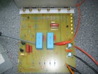
It's fired up !
Well, i am doing something wrong... (or maybee setup wrong) let's see if i can explain excatly this time
Setup 1 as this :
+36 / -36 / gnd from psu attached to pcb.
nothing at input (nothing attached to +in / -in / GND)
Voltmeter 1 attached where R13 meet's C11/C4 and where R18 meet's C12/C5. Also right before output caps (WR1 adjustment)
Voltmeter 2 attached where R18 meet's C12/C5 and GND Also right before output cap (WR2 adjustment)
Led D1 / D2 / D3 / D4 light's up now (1,8v voltage on each of them 4) Led D5 / D6 nothing (1,5volt on each on them 2)
Voltmeter 1. = ~0,2mv nothing happens when adjustning WR1.
Voltmeter 2. = 34V nothing happen's when adjustning WR2.
Is this the right way to setup adjustment. ?
Setup 2 as this :
OK I tried to attach 1000hz sine 1vpp at input +in / GND then this happens :
Led D5 / D6 light's up too now.
1000hz 1vpp at output between +out / GND. So no gain, except that the sinewave has moved a little up on the scope.
No adjustment's on WR1 / WR2 possible either now. (Voltmeter 1/2 still attached where i did at setup 1...)
Schematic http://www.diyaudio.com/forums/attachment.php?s=&postid=1247745&stamp=1183490665
Jesper.
Attachments
lykkedk said:It's fired up !
..............
Jesper.
all leds must glow in same intensity ;
they must have 5mA through them ; for that check voltage across R24 ; 5mA across 270E is ~1,35V ; double check polarity of leds
for start - WR1 on mid position ; same for WR2 ; WR2 is first thing you need to winkle
...chase zero DC from any output to gndin your case - you didn't biased CCS output mosfets ( Q6 and Q8) so you have full positive on output ........... I think so
add: my mistake - one channel current consumption is in range of ~70mA , not as I wrote previously
mpmarino said:
Duly noted.
crazy yank drekin' crazy serb ............
hehe , ya can bomb me , but ya can't be crazier than I am
Magura said:
Yeah, it's sure time for DOZM
Magura
huh ,another one............. where's Lucky Luke when man in trouble needs him ............so bad ........ ?
but ya can't be crazier than I am
....then I will stop worrying
....... where's Lucky Luke when man in trouble needs him .....
We had a DOLL session this morning, you missed it.
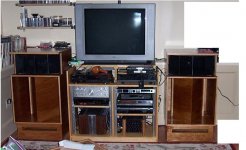
OT: I gutz dem little speaks I built into the house. Biamp w/ Klone and mini A thru a DCX2496 off a Sony ES pre for now. Um, I think you can hurt yourself with these
If you look real hard you can see the speakers...
Attachments
mpmarino said:
....
We had a DOLL session this morning, you missed it.
.
then you'll feel my revenge!!
If you look real hard you can see the speakers..
what's in these blanks at right side ?
real speakers?
what's in these blanks at right side ?
He he - the blanks were put there so you would ask!
Re: according to thread's title
Your right. I'll keep the Klone on the woofers, I think. The Klone into the 4 ohm drivers in this app seems to work better than expected. I think it could actually cause a heart attack... or maybe restart a heart. Good and tight at lower levels too. The horns are as expected - phenomenal.
The tough part is the integration between the two.
I might need to get some rta stuff together to pull it off tho. I think I'll tweak it up with the DCX2496 and then design analog stuff based on those results. Suggestions ??
Zen Mod said:
ya don't need F4 to drive that drek
Your right. I'll keep the Klone on the woofers, I think. The Klone into the 4 ohm drivers in this app seems to work better than expected. I think it could actually cause a heart attack... or maybe restart a heart. Good and tight at lower levels too. The horns are as expected - phenomenal.
The tough part is the integration between the two.
I might need to get some rta stuff together to pull it off tho. I think I'll tweak it up with the DCX2496 and then design analog stuff based on those results. Suggestions ??
Re: Re: according to thread's title
rta?
ya need Hiraga's xover schmtc for A7 , just as idea?
btw , "Klone " is as "Gainxxxxx"?
mpmarino said:
Your right. I'll keep the Klone on the woofers, I think. The Klone into the 4 ohm drivers in this app seems to work better than expected. I think it could actually cause a heart attack... or maybe restart a heart. Good and tight at lower levels too. The horns are as expected - phenomenal.
The tough part is the integration between the two.
I might need to get some rta stuff together to pull it off tho. I think I'll tweak it up with the DCX2496 and then design analog stuff based on those results. Suggestions ??
rta?
ya need Hiraga's xover schmtc for A7 , just as idea?
btw , "Klone " is as "Gainxxxxx"?
real time analyzer - spectrum analyzer
where can I find this?
Klone = Krell Ksa50 Klone
Clone = Gainxxxxx
ya need Hiraga's xover schmtc for A7 , just as idea?
where can I find this?
Klone = Krell Ksa50 Klone
Clone = Gainxxxxx
mpmarino said:.........
where can I find this?
here
ya greedy lazy crazy yank
A5, my bad ............... age........ I'm almost old as Papa and Carrot Guru
EDIT:
ya need entire article?
Attachments
in your case - you didn't biased CCS output mosfets ( Q6 and Q8) so you have full positive on output ........... I think so
ZenMod ? I don't understand this

Well, i will give up for today. This is how far i am now.
I can make all led's light up now(Suddently D5/D6 light up, when i adjusted a little).... voltagedrop below R24 is 1,2v.
DC between GND and +out is ~12vdc and the same on GND to -out (adjusted to this value's by WR2) If i go lower on e.g -out the value raises on +out... With WR1 i can set offset between +out / -out to near zero, but it seems to pendel a little up/down.
Still no gain, when attaching 1kHz sine 1v on input, the same wave appears on output.
Could you perhaps give me some meassuring point or any thing i can chase for
I now have no clue where to look.
Jesper.
- Home
- Amplifiers
- Pass Labs
- Pumpkin Preamp - Perfect for F4