
I thought it might appeal to the ZM sense of humor. ")
I am stuck on transformer choices in the USA:
Option 1:
Hammond 166G100 -- 115V 60 Hz., 50VA, 100 C.T. - $36 -- .9kg
Option 2:
2 pieces Hammond 166G100 -- 50VA, 100V C.T. - $72, -- 1.8 kg
Option 3:
Signal Transformer 80-1 -- 160 VA, 80V C.T -- $40, 1.8kg
Option 4:
A salvaged monster of a transformer with +/- 44v that weighs 4kg.
Using one Hammond is a bit light on power (50VA vs Minimum 60VA). I am inclined to go with option 2 with one transformer per chanel. Is there a compelling reason to pick another option?
power consumption of Pumpkin is around 5W per rail, so 10W for channel
25VA/per channel xformer is more than good, if you choose good one
if possible, go with Toroid type, if xformers are going in same case with rest of preamp
no need to go over 80Vct, everything above that will go in unnecessary heat
25VA/per channel xformer is more than good, if you choose good one
if possible, go with Toroid type, if xformers are going in same case with rest of preamp
no need to go over 80Vct, everything above that will go in unnecessary heat
I went with the trasformer below (it is 40-0-40 per conversation with Antek).
AS-0540 - 50VA 40V Transformer - AnTek Products Corp
And a steel case / cover out of an abundance of caution:
CA-050 Steel Cover - AnTek Products Corp
AS-0540 - 50VA 40V Transformer - AnTek Products Corp
And a steel case / cover out of an abundance of caution:
CA-050 Steel Cover - AnTek Products Corp
is there anything bellow 80Vct , with less power?
in that case , you can go with little smaller value for rails, say that 30Vdc is equally good as 36Vdc
ideal case is one xformer per channel (only that way you'll retain benefits of separate GND for each channel), as I said - no more than 25VA needed
in that case , you can go with little smaller value for rails, say that 30Vdc is equally good as 36Vdc
ideal case is one xformer per channel (only that way you'll retain benefits of separate GND for each channel), as I said - no more than 25VA needed
Finally I am pulling all my parts out of the drawer and putting together the Pampkin, am I too late to join the party? I saw mumbling of Iron Pumpkin and I have no idea what that might be but for now I will close my eyes and march forward!
I found this transformer readily available...
https://www.digikey.ca/en/products/detail/triad-magnetics/VPT36-1390/2090072
Kind of overkill at 50VA but it seems to be the best match Digikey has to offer, I will get two and run in series for 36V for both channels. Is this right?
My source is the 1.4Vrms single ended output of Soekris dam1021, I am not sure whether or not to go 10x or 15x gain. This Pumpkin will be driving a pair of F4's with balanced output, so this is my last chance for voltage gain in my chain. Normally I will not need so much gain, just need to party every once in a while. Any downside to running so much gain if I'm usually listening at normal levels? I should also note that this Pumpkin will also be used with another F4 for headphone operation.
If I go 15x gain, I was not able to find a ~3.3pF mica cap as per my calculation. Will a 3pF cap make due if I use 150kOhm on R5 and R6?
ie. https://www.digikey.ca/en/products/detail/cornell-dubilier-electronics-cde/CD15CD030DO3F/1917712
Also I'd like to share a monster heatsink I've found, which will cut into pieces nicely to work with Pumpkin and Shunty for reasonable price.
https://www.digikey.ca/en/products/detail/advanced-thermal-solutions-inc/ATS-EXL1-254-R0/5848401
I finally got back to my shunty and pumpkin boards. I bought the pcbs and the "A" package (incl. matched IRF outputs) from ZenMod in 2017. Some years ago I soldered all the parts onto the boards but never tested or finished them. I got stuck figuring out how to fit everything (incl. remote volume control and input selection) into the box I had waiting for it, and ended up putting everything in a container until I had more inspiration.
Having built a few more things since then (and learning that sometimes things are a pain to debug once they are screwed into the box) I decided it would be better to test the amp first with the pcbs screwed to some plywood and leave the remote controlled input etc. for another time. Also, I now think I will solve the space problem by putting the transformers and shunties in a separate box, removing the risk of noise (and add some capacitance to the pumpkin rails to compensate for the distance).
Shunty
I have 2 shunties, so 4 rails. With the 470R resistors in place I could set all rails to 36V. While the output is stable on 3 rails, the voltage fluctatutes seemingly randomly (max. about +/- 200mV) on one positive rail.
It was late and cold in my shed, so I did not measure anything else. My helper (I am in a wheelchair) won't be back for a few days, so this is a good time to figure out what it could be and make a plan.
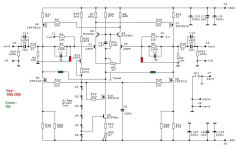
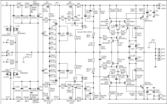
I have noticed that there are multiple schematics of the pumpkin and shunty on the forum (not all marked with a date or revision), so best to include that I used the schematics and bom from the Pumpkin & Shunty PDF that, according to the file properties, was last modified 20-JUL-2012 (see screenshot and attached file).
Pumpkin
I could not hesitate to see if I could set the voltages on the pumpkins, but could not get below say 25V difference when the 25 turn pot maxed out. I have since been reading and realise I made a stupid mistake when I soldered the parts. I did not have enough green leds, so (not realising the importance) used 3 green and 3 yellow leds (D1-3 green, D4-6 yellow). I assume I need to replace the yellow with green?
But, I did read somewhere that not all green leds specify as 1V93. So, just replacing the yellow by the greens I havein my drawer may not be the best option.
I understand the total drop across D1-D5 is supposed to be 5 x 1V93 = 9V65 while the drop across D6 is supposed to be 1V93. I have not measured my leds yet, but would like to know which voltages for D1-5 and D6 resp. are acceptable.
Also, is green the most quiet (and the reason it was chosen) or will any color do (as long as the total voltages are in spec)?
Thanks!
Having built a few more things since then (and learning that sometimes things are a pain to debug once they are screwed into the box) I decided it would be better to test the amp first with the pcbs screwed to some plywood and leave the remote controlled input etc. for another time. Also, I now think I will solve the space problem by putting the transformers and shunties in a separate box, removing the risk of noise (and add some capacitance to the pumpkin rails to compensate for the distance).
Shunty
I have 2 shunties, so 4 rails. With the 470R resistors in place I could set all rails to 36V. While the output is stable on 3 rails, the voltage fluctatutes seemingly randomly (max. about +/- 200mV) on one positive rail.
It was late and cold in my shed, so I did not measure anything else. My helper (I am in a wheelchair) won't be back for a few days, so this is a good time to figure out what it could be and make a plan.
I have noticed that there are multiple schematics of the pumpkin and shunty on the forum (not all marked with a date or revision), so best to include that I used the schematics and bom from the Pumpkin & Shunty PDF that, according to the file properties, was last modified 20-JUL-2012 (see screenshot and attached file).
Pumpkin
I could not hesitate to see if I could set the voltages on the pumpkins, but could not get below say 25V difference when the 25 turn pot maxed out. I have since been reading and realise I made a stupid mistake when I soldered the parts. I did not have enough green leds, so (not realising the importance) used 3 green and 3 yellow leds (D1-3 green, D4-6 yellow). I assume I need to replace the yellow with green?
But, I did read somewhere that not all green leds specify as 1V93. So, just replacing the yellow by the greens I havein my drawer may not be the best option.
I understand the total drop across D1-D5 is supposed to be 5 x 1V93 = 9V65 while the drop across D6 is supposed to be 1V93. I have not measured my leds yet, but would like to know which voltages for D1-5 and D6 resp. are acceptable.
Also, is green the most quiet (and the reason it was chosen) or will any color do (as long as the total voltages are in spec)?
Thanks!
Attachments

pretty much any LED with ref voltage in range of 1V8 to 2V will do
did you apply few remedies, written & shown on last page of Cookbook?
I presume these are schm you're using:
did you apply few remedies, written & shown on last page of Cookbook?
I presume these are schm you're using:
Attachments
Thanks ZenMod.
I used the schematics in the pdf file but did not do the changes yet that are listed at the back. Now that I know the voltage I am aiming for, I hope the pumpkins will not be a problem. I have an Aliexpress gadget that should make testing the voltage of the leds I have easy.
Do you have any suggestions regarding the fluctuating voltage in one + rail of one of the two Shunty?
don't bother with measuring voltages of LEDs, except to check that they aren't of modern variety LEDs (having both wakoo voltage and current and light)
OK if you have very useful chinese Gizmo, testing is fast and easy
now - Shunty - you can check it in blocks, to determine where problem is; and there must be a problem with something ( wrong part value, orientation, bad solder)
say - if you open JP1, you must have proper voltage at output of series reg part (zener source follower), which is value of zener string decreased by Ugs of IRF; practically 5*10V-4V=46V
few volts up or down is normal, taking in account tolerance of zeners
confirm that, then we can proceed
Thanks. I have to wait until my helper is here (Thursday) before I can do testing.
All 3 other shunty rails have steady voltage, so it is not a systemtic error and the active parts cannot be mixed up because the others work (I bought your "A" package and had nothing left over ).
The voltage at the output is correct (36V), I just see fluctuation on my 4 digit fluke that I do not see on the other 3 rails. Not limited by knowledge, my guess would be that something is oscillating and causing the voltage to fluctuate max. +-200mV around the intended value of 36V.
All 3 other shunty rails have steady voltage, so it is not a systemtic error and the active parts cannot be mixed up because the others work (I bought your "A" package and had nothing left over
).The voltage at the output is correct (36V), I just see fluctuation on my 4 digit fluke that I do not see on the other 3 rails. Not limited by knowledge, my guess would be that something is oscillating and causing the voltage to fluctuate max. +-200mV around the intended value of 36V.
- Home
- Amplifiers
- Pass Labs
- Pumpkin preamp - ordered by Steen , official making thread