believe me - that cap is beneficial only if smallest one is used
ceramic is perfect , but use whatever you have in drawer
as I said - start from 1nF upwards
regarding visit to Italia .......... who knows ...... all roads are heading to Rome , anyway
Ok tomorrow it will be the first thing I do.
I recently live near Milano,so you should consider the idea to visit the next TOP AUDIO nex September.
But this is an other story

Thanks and good night!
Last edited:
Hello Alex! the stuff may you seem strange, but I tried using a 4.7 nF
and I got a result slightly inferior that obtained with 1uF.
Logically, I carried out an analysis of all the frequency range Hz kHz MHz and found that in the range of kHz 1uF gives better results than 4.7 nF.
So now i decided to leave 1uF.
Now i need a good layout cables assembly.
Please can you give me same good link or informations, if you prefer, also in Private Post.
Thanks
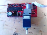
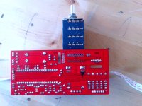
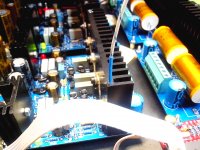
Hi Alex i will use the input selector and volume control showed in pictures attached (red pcb).
I had to change a few things to be able to make it suitable for balanced use . I also have replaced its original pot with a four-way 10K Alps (much better than the original).
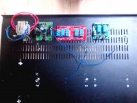
In this way i will get the same functionality of the input selector shown in the last picture more the possibility of remote control.
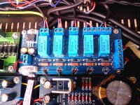
In the third picture the last pcb on the right will serve to keep the outputs to ground for a few seconds (about 10) to avoid bump input to the power amp.
What do you think of this device?
I had to change a few things to be able to make it suitable for balanced use . I also have replaced its original pot with a four-way 10K Alps (much better than the original).
In this way i will get the same functionality of the input selector shown in the last picture more the possibility of remote control.
In the third picture the last pcb on the right will serve to keep the outputs to ground for a few seconds (about 10) to avoid bump input to the power amp.
What do you think of this device?
Attachments
Last edited:
I did replied , but can't do again , because I deleted plenty of messages in my box
write here
The question is about C5 1nF Polyester (as project) or 1nF Silver Mica (can it be a upgrade) or without C5 (can the amp be yet stable or not),in this last case how i can check if it is yet in sure zone?
check for oscillations on output with CRO
if you don't have any , don't use these 1nF
if you need them - put whatever you have in drawer - no need for mica
Sorry! What is CRO?
I need to use the oscilloscope and signal generator with 100hz 1khz and 10khz signal input?
Tony
for start - if you're not having enough praxis with CRO , just connect this (attached) across spk terminals,of course - with amp powered on
in silent , then with some light level muzak
if LED's are silent , you're good to go , without those two 1nF caps
for start - if you're not having enough praxis with CRO , just connect this (attached) across spk terminals,of course - with amp powered on
in silent , then with some light level muzak
if LED's are silent , you're good to go , without those two 1nF caps
Attachments
Cathode Ray Oscilloscope (CRO) ...Good to know,thanks Andrew!
About CRO use...i can try to find the power switch and after i can try also to do something more...but Alex i have to tell you ..."you know always something more of Devil" What mind had designed this circuit..almost doubt (for its simplicity) that will work!
Thanks Alex and Andrew!
About CRO use...i can try to find the power switch
and after i can try also to do something more...but Alex i have to tell you ..."you know always something more of Devil" What mind had designed this circuit..almost doubt (for its simplicity) that will work!Thanks Alex and Andrew!
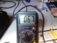
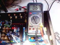
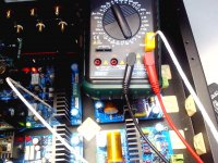
About shunty heatsink temperature
Hi at all! Please is normal about 70° measured on heatsink of shunty (no load connected and cover open ) ,or i have to add more alluminium sink?
Thank in advance
Antonio
Hi at all! Please is normal about 70° measured on heatsink of shunty (no load connected and cover open ) ,or i have to add more alluminium sink?
Thank in advance
Antonio
Attachments
Last edited:
without load , everything is dissipated on Shunty itself
when you connect load , dissipation will go down ........
so , just relax
Thanks Alex!
I supposed instead that connecting the load shunty would collapse!
Sorry my mistake

- Home
- Amplifiers
- Pass Labs
- Pumpkin preamp - ordered by Steen , official making thread