Evening all...
Today i tried to cut some unused gnd (black wire's) connection, and this way i got rid of the visible hum, seen on my CRO!
Humm stil happens though, now it just can't be seen anymore")
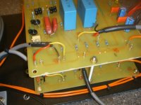
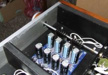
I attached a picture of my initial setup.
Middle just below blue output cap's you can see the cutout black gnd.
It's very hard to explain how i attach everything on picture's.
But i will try anyway:
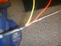
The 2 orange wire on right picture is pwr-gnd goes to 'star' gnd.
Going from right to left on picture, red wire is +out which goes to +out(rca for now) Yellow goes to -out (attached on gnd rca connection at end of cable) RCA connectors gnd goes to 'star' gnd.
Left picture the input connection's are located. yellow = -in , black=sgnd , red=+in
All 3 goes to 4deck attennuator.
On input rca, the gnd goes to 'star' gnd.
Yellow is attached to gnd too, at my testsetup.
Don't think my description could be usefull though...
Jesper.
Today i tried to cut some unused gnd (black wire's) connection, and this way i got rid of the visible hum, seen on my CRO!
Humm stil happens though, now it just can't be seen anymore
I attached a picture of my initial setup.
Middle just below blue output cap's you can see the cutout black gnd.
It's very hard to explain how i attach everything on picture's.
But i will try anyway:
The 2 orange wire on right picture is pwr-gnd goes to 'star' gnd.
Going from right to left on picture, red wire is +out which goes to +out(rca for now) Yellow goes to -out (attached on gnd rca connection at end of cable) RCA connectors gnd goes to 'star' gnd.
Left picture the input connection's are located. yellow = -in , black=sgnd , red=+in
All 3 goes to 4deck attennuator.
On input rca, the gnd goes to 'star' gnd.
Yellow is attached to gnd too, at my testsetup.
Don't think my description could be usefull though...
Jesper.
Attachments
I use to do it that way. I usually have less hum problems with it.OR just a pair, twisted ?
Ok, basic question. Do people mostly use shielded wire for internal hookups? say for the wire that goes internally from a phono jack to the circuit board? OR just a pair, twisted ?
This could be a whole thread by itself.
For internal wiring, I just use wire, not even a twisted pair.
What does the twisting together do, really? I noticed with shielded microphone (balanced) cable (the kind PE sells for making XLR interconnects) that if I feed a signal in one wire, I can easily read the signal in the wire running parallel to it, but with a slight phase difference.... even when the parallel wire was connected to ground through a 600 ohm resistor.
To me, this says there is a lot of capacitive coupling between the two wires, and I haven't been able to convince myself of any reason why this would be good.
JJ
jupiterjune said:
To me, this says there is a lot of capacitive coupling between the two wires, and I haven't been able to convince myself of any reason why this would be good.
JJ
Common mode rejection?
lykkkkk
are you hiding in some danske igloo doing some things for family augmenting , or you hiding decreasing gain or...........
Your'e right master ZenMod... family buissnes, work and such thing's is due to my silence.. last few day's.
Problem with gian't noise, hum is nearly solved by now, last funny thing with sensitivity with my 20x gain / no chassis / leachamp, i agree with you, is the comparing to use a pre with a mm/mc input. The reason why some noise/sensitivity appear's when closing -in to gnd, must be that the gain raises som xxx factor while doing this. Right now i must find time to make rest of chassis / inputselector and try all this. (maybee before christmas???) donno.
Going from big big big problem's with this setup/leachamp down to allmost nothing, is that i used the grounding schm. you drawed earlier in thread.
I am hoping that i can try it out some more next few day's.
Jesper.
lykkedk said:
Your'e right master ZenMod... family buissnes, work and such thing's is due to my silence.. last few day's.
Problem with gian't noise, hum is nearly solved by now, last funny thing with sensitivity with my 20x gain / no chassis / leachamp, i agree with you, is the comparing to use a pre with a mm/mc input. The reason why some noise/sensitivity appear's when closing -in to gnd, must be that the gain raises som xxx factor while doing this. Right now i must find time to make rest of chassis / inputselector and try all this. (maybee before christmas???) donno.
Going from big big big problem's with this setup/leachamp down to allmost nothing, is that i used the grounding schm. you drawed earlier in thread.
I am hoping that i can try it out some more next few day's.
Jesper.
did you finally hear
 with Leach?
with gain of ,say, 5 ........
did you finally hear with Leach?
YesYes... no problem... but with gain 20~25
 ... only slight hum... only volume at max!!! 1/4
 Jesper.
Re: to obtain a right to email
whatever road you choose , it will take you to the Rome ........
you can always reach choky at >choky@neobee.net<
copy and paste that between the >< brackets

jkchoi said:
Still the log box tell me that I have to write post more in order to email direct to him.
So, I had to describe my need to him, before long he will be received email.
whatever road you choose , it will take you to the Rome ........
you can always reach choky at >choky@neobee.net<
copy and paste that between the >< brackets
rail voltage
I have a xformer having two 0-30V AC .
I think the shunt regulator also has a important roll for the qualified sound. So, I do not want to replace it to the simple one having higher output voltage although the shunt has a big voltage drop and the voltage swing needed for F4 will be around +-20V.
But I understand that the sound quality can change by the rail V.
Choky what is your recommendation New Xformer or Change V?
In fact my F4 has 15V AC xformer. So, the rail voltage is around 18V during running. But having great sound quality. It has powerful enough. I would like to make a balaced F4 later to see what happens.
So, at this moment I want to challenge to down the rail voltage of pumpkin pre and shunt regulator also.
Let's see...........
24V can be adequate as output of shunt, so called for rail.
Too long later
Re: rail voltage
so - 2x30 will give ya ~ 2x40 V on caps ........... I think that we can cut this to healthy 2x28V without penalties ........ under condition that your mains voltage isn't too variable going down
it's easy to change few things to accommodate that ..........
ya see that never is too late ..............
jkchoi said:I have a xformer having two 0-30V AC .
I think the shunt regulator also has a important roll for the qualified sound. So, I do not want to replace it to the simple one having higher output voltage although the shunt has a big voltage drop and the voltage swing needed for F4 will be around +-20V.
But I understand that the sound quality can change by the rail V.
Choky what is your recommendation New Xformer or Change V?
In fact my F4 has 15V AC xformer. So, the rail voltage is around 18V during running. But having great sound quality. It has powerful enough. I would like to make a balaced F4 later to see what happens.
So, at this moment I want to challenge to down the rail voltage of pumpkin pre and shunt regulator also.
Let's see...........
24V can be adequate as output of shunt, so called for rail.
Too long later
so - 2x30 will give ya ~ 2x40 V on caps ........... I think that we can cut this to healthy 2x28V without penalties ........ under condition that your mains voltage isn't too variable going down
it's easy to change few things to accommodate that ..........
ya see that never is too late ..............
for 30V AC xformer
R23,24 for CRC will be OK or reduce to 3E3
I don't know about OS1 300mA no idea!, pass
Q1,Q2 IRF 510 will be changed to IRF 610, or 540 (because I have it)
D1-D5 ZY10 will be changed to 4X9.1V=36.4V
R7 for safety will be same, pass
D8 LED will be somwhat dimmy!!, pass
R8 68k, WR1 4k7,R9 6k8 will be changed to 24k, 2k, 4.7k because I have them and can bring ~23-30V out
R13 27k will be changed to 15k then the base of the
Q6,7 will be around 15V-17V
Q10 can be changed to 2SK246 with R19 680? for 1mA ccs and R18 22k can be changed to 15k for safety
But finally I have no BDX54(p-darligton), can I replace it to any p-type darlington with collector dissipation 60W around?
Hi Choky...
As you know i was fizzling around with gainsetting's / LeachAmp ... and all that !
I have ended up with gainsetting at ~ 147,5K / 6,2K = ~23x (R1, R5 / R3, R6) for giving me enough power for my setup with voltagehungry F4's.
I am having the idea to put in a serie-resistor at input R1/R3 for lowering the gain, if i will use with another amp, than F4.
Will it be a bad idea to put in e.g 4K (plus them 6,2k i have now, which will give me 10,2K on input) - this will lower the gain from ~23x to ~14,4x ??? Or must value's R1/R5 , R3/R6 follow each other if you know what i mean.
I assume this will not effect the adjustment's of the, as this only will be like replacing the attennuator i think only thing what happens is a higher resistance on input ... hope you understand what i mean!
Well i will pull in a switch to either short or add this extra resistor having the name perhaps ------> '' Pumpkin superamp , normal cheap discount's amp's¨¨ switch.
Jesper.
As you know
i was fizzling around with gainsetting's / LeachAmp ... and all that !I have ended up with gainsetting at ~ 147,5K / 6,2K = ~23x (R1, R5 / R3, R6) for giving me enough power for my setup with voltagehungry F4's.
I am having the idea to put in a serie-resistor at input R1/R3 for lowering the gain, if i will use
with another amp, than F4. Will it be a bad idea to put in e.g 4K (plus them 6,2k i have now, which will give me 10,2K on input) - this will lower the gain from ~23x to ~14,4x ??? Or must value's R1/R5 , R3/R6 follow each other if you know what i mean.
I assume this will not effect the adjustment's of the
, as this only will be like replacing the attennuator i think only thing what happens is a higher resistance on input ... hope you understand what i mean!Well i will pull in a switch to either short or add this extra resistor having the name perhaps ------> '' Pumpkin superamp , normal cheap discount's amp's
¨¨ switch.Jesper.
lykkedk said:Hi Choky...
As you know
I have ended up with gainsetting at ~ 147,5K / 6,2K = ~23x (R1, R5 / R3, R6) for giving me enough power for my setup with voltagehungry F4's.
I am having the idea to put in a serie-resistor at input R1/R3 for lowering the gain, if i will use
Will it be a bad idea to put in e.g 4K (plus them 6,2k i have now, which will give me 10,2K on input) - this will lower the gain from ~23x to ~14,4x ??? Or must value's R1/R5 , R3/R6 follow each other if you know what i mean.
I assume this will not effect the adjustment's of the
Well i will pull in a switch to either short or add this extra resistor having the name perhaps ------> '' Pumpkin superamp , normal cheap discount's amp's
Jesper.
you are almost as me ........ ya cheapskate, dumpster diver , ya junkyard abuser!
hehe - you'll never learn - it's easier and more convenient to make two different systems - one for each side of room ,or one for each room , than making universal huperduper gizmo
place 27k in series with 6K2 , and switch across 27K ; you don't need that amount of gain for poor leachie ......... ya wanna kill either leachie or poor cones ..........?!
An externally hosted image should be here but it was not working when we last tested it.
An externally hosted image should be here but it was not working when we last tested it.
mpmarino said:
...
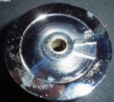
I'm really disappointed with the way the knobs feel - too wobbly. They are large solid alu and don't feel right hanging off of a junkyard motorized pot and input selector. I'm building a bearing carriage with stainless shafts for the assembly to eliminate play and make 'er bullet proof..
put selector and pot on back of uckin' fugly case, and make extending shafts from front plate to back;
you can drill bigger holes in front plate and put bearings as shaft guides ...... if ya're nutzzzzzzzzz ....... look at Igor's preamp thread ;
or - be smart
and use messing as guidesedit:
http://www.diyaudio.com/forums/showthread.php?postid=1340228#post1340228
Attachments
Zen Mod said:
put selector and pot on back of uckin' fugly case, and make extending shafts from front plate to back;
you can drill bigger holes in front plate and put bearings as shaft guides ...... if ya're nutzzzzzzzzz ....... look at Igor's preamp thread ;
or - be smart
edit:
http://www.diyaudio.com/forums/showthread.php?postid=1340228#post1340228
Naahh! Already been done.
I'm using two bearings per 'axle' with thrust washers to eliminate all play
Relay set-ups for atten and select so no shafts thru da case allowed or needed..
.....gotta come up with a clutch for the atten motor. I'm still 'junkin' for parts for the boards, so no time lost
edit: What is messing (well, in a preamp!)
mpmarino said:the knobs feel - too wobbly.
Making them hollow is my preference, i enjoy big knobs (read as you please)
Shrinking a hollow body on a solid base is easy, machine the inside edge of the knob body and there's no seam in sight.
Brass can be welded, then polished and chromed =>
Attachments
jacco vermeulen said:..........
Wooha,...how's about Hitachibachies instead of the 510/9510s, wouldn't that make a Smashing...Pineapple ?
which one Hitchies , when we are almost at the gate?
if y awann ause that rar edrek , then you can use :
2SK170V instead of J310
2SC2240 ----- BC546
Hitchies instead Irfies
........ with necessary decreasing of input LTP's drain resistors ( Hitchies have lower Ugs ?) , you'll decrease OLG ......... and decrease SS ......... but - who knows ,maybe you'll hit Graal , even without UGSlikeeeeeee or FTBlikeeeeee construction/approaches
Papa ( AKA Master of Lateral thinking, AKA My Back Of Napkin Is your Wettest Dream ) must be laughing now ........
dunno ........ I 'm under impression that Irfies aren't that worse that Hitchies ........... give them 75mA on each side , and you'll never hear difference
my FBT is better than your FBT
I'll send ya muni in next few days , ya fylthy rych bych , just because ya always tickle my IQ
Attachments

- Status
- Not open for further replies.
- Home
- Amplifiers
- Pass Labs
- Pumpkin preamp - More Boring Making Thread