Re: hehehehehe
Look who's talking. Try to get some real work done for a change

Like this:
Zen Mod said:
Look who's talking. Try to get some real work done for a change
Like this:
Attachments
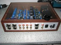
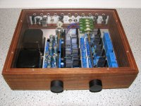
Not quite finished yet, but all the mechanical stuff and supports are done.
Here is a pic of the current state. Simple does it, I am striving for a very clean look, now that the lid is see-through The faceplate has 2 black knobs and one green (! not blue, for a change) LED.
Here is a pic of the current state. Simple does it, I am striving for a very clean look, now that the lid is see-through
The faceplate has 2 black knobs and one green (! not blue, for a change) LED. Attachments
steenoe said:
.......
Naa, ZM is not easily impressed.....
..........
ya know that I'm proud of you and your results with my (what else than ) modest efforts
that's why I'm asking lately that you send me high res pics ; these small ones aren't good enough for my pride

steenoe said:
........Dont know why, considering the messy stuff he builds, himself....he-he....
..........
blahblah
 ya already know that I'm not building anything .....
 but - if I remember that good - your Bab was certainly one of ugliest amps on Pass subforum ,and certainly your ugliest amp ...........

edit :
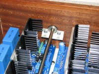
I like these htsnks ; leave them , if they are enough , temp wise .......
Zen Mod said:
ya know that I'm proud of you and your results with my (what else than ) modest efforts
that's why I'm asking lately that you send me high res pics ; these small ones aren't good enough for my pride
blahblah
but - if I remember that good - your Bab was certainly one of ugliest amps on Pass subforum ,and certainly your ugliest amp ...........
edit :
I like these htsnks ; leave them , if they are enough , temp wise .......
He-he, My Babbelfish was ugly, but it did sound better than all the other amp's.I build things,two perspectives: 1) I want to know how it sounds, kind of build.
2) This is good, I am gonna keep it, kind of build. The Pumpkin is in category 2)
Just in case you didnt figure that out, yourself I hope that with the ballbearings and all that, it will "Pass" on to my son ( Well,one of them
) In perfect working condition.... Yep the "finger" heatsinks does look like they belong, now that I have mounted 12 of them. If it works out temp. wise, I might keep them. It was a heck a work to install them ....
My Aleph-X monoblock's are another category 2 build
Take a lookAttachments
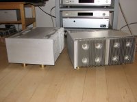
The A-X's really do like the Pumpkin, I think that the voltage gain in the A-X's is pretty low??
Is this comment true, If so this will be on the drawing board.
Cheers
Dan
freakyone said:
Is this comment true, If so this will be on the drawing board.
Cheers
Dan
Sorry 'bout the late answer, it will be short since my shoulder is killing me..... again!
I am not sure how much gain the A-X's has, what I do know is that they sound much better with the Pumpkin. A More dynamic and authoritive sound, so to speak.
yggdrasil said:Zen Mod is there a reason you have used darlingtons in the shunt part of shunty in stead of e.g. 510/9510's?
BTW: The pumpkins are soldered, working on the shuntys.
yup- there is a reason - better voltage stability , tested in
no load/load conditions ;
meaning that in no load state Shunty must eat every mA pushed through his own CCS ( hehe - in simple words - there is no external load on Shunty's output)
anyway - I have impression that Shunty is even in this way good enough

housing said:Hello Choky,
Will 18Ø*35.5mm pitch:7.5mm caps fit the Shunty?
Yes they will just fit. But 18 mm Diameter is max. (smaller fits better)
If 63V is enough depends on the voltage coming out the rect. bridge.
Mine are 100V
Manu
Re: Inductor DIY
in most cases just mileage (xperience) can tell what is right mix of L/Rdc/cost/dimensions you'll choose
usually :
L - more - the merrier
Rdc - depending of overall I your circ is sucking , sometimes you want to burn few V more in choke itself etc ....... but without overheating it
and - overheating is directly related to -cost- and -dimensions- , which we usually want to keep veeeeeeery low . both of them
anyway - Magura-san is man of big words (mouth?) and big chokes ; probably just because he just don't have small machines for winding , so he just must use big cores/formers and thick wire
in any case - if you are cheapskate as I am , you'll find as much you can old xformers and use them for winding ;
I wrote numerous times exact recipe how to make nice little 8-10mH choke for CLC filters , good up to 5-6 amps......
anyway - just shoot with exact question and I'm sure that someone will be smart enough to write few words as answer ........
edit:
big currents (say above 500mA ) - think in mHenries
small currents (say below 500mA ) - think in Henries
zettelsm said:
Thank you, ZM. Good calculator. However I was hoping for some application background, like (electrical) size and what other factors would be important for power supply inductors -- like for the Pumpkin-Shunty for example.
Or your own tube preamp. . .
Thanks,
Steve Z
in most cases just mileage (xperience) can tell what is right mix of L/Rdc/cost/dimensions you'll choose
usually :
L - more - the merrier
Rdc - depending of overall I your circ is sucking , sometimes you want to burn few V more in choke itself etc ....... but without overheating it
and - overheating is directly related to -cost- and -dimensions- , which we usually want to keep veeeeeeery low . both of them
anyway - Magura-san is man of big words (mouth?) and big chokes ; probably just because he just don't have small machines for winding , so he just must use big cores/formers and thick wire
in any case - if you are cheapskate as I am , you'll find as much you can old xformers and use them for winding ;
I wrote numerous times exact recipe how to make nice little 8-10mH choke for CLC filters , good up to 5-6 amps......
anyway - just shoot with exact question and I'm sure that someone will be smart enough to write few words as answer ........
edit:
big currents (say above 500mA ) - think in mHenries
small currents (say below 500mA ) - think in Henries
Re: Re: So tell us more. . .
I don't agree. Lalena is not optimized. You get higher DCR and spend way too much copper.
Magura
Zen Mod said:
just google for "lalena online calc"
it's good enough
I don't agree. Lalena is not optimized. You get higher DCR and spend way too much copper.
Magura
Re: Re: Inductor DIY
Thanks Mr. Magura -- that is the problem though, I am too dumb to know what specs are important right now (DCR obviously) or what kind of mH makes sense for I and E of a given power supply.
What I would like to do is wind myself some inductors to use with the Pumpkin Shunty preamp. Longer term, I would like to learn enough so that I can properly size and build inductors for tube power supplies. . .
I dont want someone to just give me the answer, I would like to learn how to figure out the answer myself.
Steve Z

Magura said:
Give me some specs to meet, and I'll tell you how to meet them
Magura
Thanks Mr. Magura -- that is the problem though, I am too dumb to know what specs are important right now (DCR obviously) or what kind of mH makes sense for I and E of a given power supply.
What I would like to do is wind myself some inductors to use with the Pumpkin Shunty preamp. Longer term, I would like to learn enough so that I can properly size and build inductors for tube power supplies. . .
I dont want someone to just give me the answer, I would like to learn how to figure out the answer myself.
Steve Z
@zettelsm :
if you already didn't , go to www.duncanamps.com and download PSUD
play and learn ;
then - with few occasional questions , you'll be able to make things
btw - for Pumpshe - anything as choke will suffice , with Rdc not greater than -say-10 ohms
if you already didn't , go to www.duncanamps.com and download PSUD
play and learn ;
then - with few occasional questions , you'll be able to make things
btw - for Pumpshe - anything as choke will suffice , with Rdc not greater than -say-10 ohms
Re: Re: Re: Inductor DIY
Well, to be able to help you, we gotta limit your question a bit.
If you want to make inductors for your pumpkin, fine be it
I would suggest a CLC filter of 10.000uF-5mH-10.000uF.
Now we gotta figure if we want dual supplies, or common supply for both channels.
Next, what sort of wattage are we looking at here?
Then we go on to making the respective trade-offs, of loss VS. size VS. cost.
The last step of actually winding the little critter, is the pretty much defined by the above
Magura
zettelsm said:
Thanks Mr. Magura -- that is the problem though, I am too dumb to know what specs are important right now (DCR obviously) or what kind of mH makes sense for I and E of a given power supply.
What I would like to do is wind myself some inductors to use with the Pumpkin Shunty preamp. Longer term, I would like to learn enough so that I can properly size and build inductors for tube power supplies. . .
I dont want someone to just give me the answer, I would like to learn how to figure out the answer myself.
Steve Z
Well, to be able to help you, we gotta limit your question a bit.
If you want to make inductors for your pumpkin, fine be it
I would suggest a CLC filter of 10.000uF-5mH-10.000uF.
Now we gotta figure if we want dual supplies, or common supply for both channels.
Next, what sort of wattage are we looking at here?
Then we go on to making the respective trade-offs, of loss VS. size VS. cost.
The last step of actually winding the little critter, is the pretty much defined by the above
Magura
Re: Re: Re: Re: Inductor DIY
Well, thanks!
Here are some of the parameters --
dual mono power supplies
wattage: I will have to go back through some of the posts. I think we are taking about about 40VA a channel (guessing)
trade-offs: (most important to least): loss, size, cost
Question: (betraying the true depths of my ignorance about power supply chokes) Is it possible to use a choke with ZMs existing boards, inserting it where he left an "opening" in the power supply section before the regulator circuitry?
Thanks in advance for the lesson, Magura-san!
Steve Z
Magura said:
Well, to be able to help you, we gotta limit your question a bit.
If you want to make inductors for your pumpkin, fine be it
I would suggest a CLC filter of 10.000uF-5mH-10.000uF.
Now we gotta figure if we want dual supplies, or common supply for both channels.
Next, what sort of wattage are we looking at here?
Then we go on to making the respective trade-offs, of loss VS. size VS. cost.
The last step of actually winding the little critter, is the pretty much defined by the above
Magura
Well, thanks!
Here are some of the parameters --
dual mono power supplies
wattage: I will have to go back through some of the posts. I think we are taking about about 40VA a channel (guessing)
trade-offs: (most important to least): loss, size, cost
Question: (betraying the true depths of my ignorance about power supply chokes) Is it possible to use a choke with ZMs existing boards, inserting it where he left an "opening" in the power supply section before the regulator circuitry?
Thanks in advance for the lesson, Magura-san!
Steve Z
Re: Re: Re: Re: Re: Inductor DIY
Ok, so we want to make those inductors real big. For 40W you can get away with 0.42mm magnet wire, but for low DCR, simply go all the way and use 1.9mm, this should give you a DCR around 0.5 (rough estimation). 1.9mm wire is the treshold in my book, where itt turns too cumbersome to do the winding. If bigger wire is required, simply use several runs.
Now run the numbers in this little nifty application
http://tek.bke.hu/kepek/inductor.exe
5mh, 1.9mm wire, and simply play around with the other factors till you get the lowest DCR.
As for the shunty boards, they are CRCRC, so just replace the first R with L
Once you have this figured, the rest is a purely mechanical challenge
Magura
zettelsm said:
Well, thanks!
Here are some of the parameters --
dual mono power supplies
wattage: I will have to go back through some of the posts. I think we are taking about about 40VA a channel (guessing)
trade-offs: (most important to least): loss, size, cost
Question: (betraying the true depths of my ignorance about power supply chokes) Is it possible to use a choke with ZMs existing boards, inserting it where he left an "opening" in the power supply section before the regulator circuitry?
Thanks in advance for the lesson, Magura-san!
Steve Z
Ok, so we want to make those inductors real big. For 40W you can get away with 0.42mm magnet wire, but for low DCR, simply go all the way and use 1.9mm, this should give you a DCR around 0.5 (rough estimation). 1.9mm wire is the treshold in my book, where itt turns too cumbersome to do the winding. If bigger wire is required, simply use several runs.
Now run the numbers in this little nifty application
http://tek.bke.hu/kepek/inductor.exe
5mh, 1.9mm wire, and simply play around with the other factors till you get the lowest DCR.
As for the shunty boards, they are CRCRC, so just replace the first R with L
Once you have this figured, the rest is a purely mechanical challenge
Magura
Re: Re: Re: Re: Re: Inductor DIY
Naah, just trying to meet his target
Once he becomes more familiar with winding, bifilar wound air cores would be the ticket.
Anyhow, the real easy solution would be ferrite core, like used for SMPS, those can carry like 1A a piece, offers like 3mH for the size of a 5W resistor. Cost like 1 ot 2 USD, so 2 in parallel should cut it.
.......but he wanted to wind his own, and he wanted low DCR
Magura
zettelsm said:
trade-offs: (most important to least): loss, size, cost
Steve Z
Zen Mod said:Magura - ya nutz
Naah, just trying to meet his target
Once he becomes more familiar with winding, bifilar wound air cores would be the ticket.
Anyhow, the real easy solution would be ferrite core, like used for SMPS, those can carry like 1A a piece, offers like 3mH for the size of a 5W resistor. Cost like 1 ot 2 USD, so 2 in parallel should cut it.
.......but he wanted to wind his own, and he wanted low DCR
Magura
- Status
- Not open for further replies.
- Home
- Amplifiers
- Pass Labs
- Pumpkin preamp - More Boring Making Thread