I used a micro to control all the functions of my preamplifier.
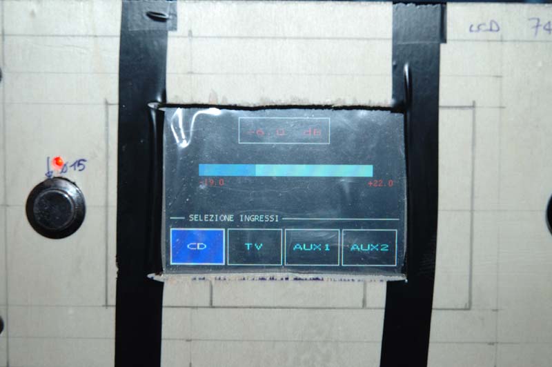
The preamp is equipped with a 3.5" (320x240 256 colors) touchscreen where the micro displays a "volume bar", the "balance bar" and the current selected input.
The volume and the balance are controlled with a rotary encoder (then no potentiometer) and a PGA2310, the selection of the input is made through the "touchscreen" feature of the LCD.
You are right...it's fun to use micros !
This is a pic of the "user interface" of the preamp (I have to put everything on a good case yet !)...
Last edited:
That it is neat. You did an excellent job. I like it. I bought some digital variable resistor long time ago from Maxim to control the volume of my preamp remotely but I have to put it aside for a while. Now that I am retired I may bring it back. I am getting tire of stand up to adjust the volume and turn it off. I have an old Dynaco 120 with PAT 4.
Hi,
This update will finalize this thread. At the beginning of this thread I explained the purpose of this thread was to explain on how a microprocessor can be use to protect the speakers from an over voltage, failure in the output transistors or due to a shorted in the speaker output connectors. My original designed was to read the speakers output voltages and determine if the mechanical relay was safe to close or to open due to a constantly high voltage feeding the speakers when the amplifier was power up or during normal operation. After various exhaustive tested done I came to the conclusion that the micro can be incorporate /used in the design of audio circuit like the speakers protection. The prototype was built using the following components:
1- NANO28 from Basic micro,
2- Omron MY2N 24 volts relay
3- TL783 voltage regulator
4- LM7805 voltage regulator
5- LH1546 solid state relay for the mute
6- MPC6022 op amp
7- TC6662 negative voltage converter
8- Printed circuit from ExpressPCB
9- ASSR-V622 Dual Channel photovoltaic MOSFET Driver
10- 4-IRF640 MOSFET transistor
11- -LM7805 voltage regulator
The prototype it is installed in my LM3886 built and it is been working flawless with no problems for almost 2 months.
Thing that the micro was programmed to do.
1- Delay the amplifier in the power up to allow the PS voltages settle.
2- Enable/disable the amplifier Mute
3- Check both output channel voltages if it is safe to close the output relay.
4- Constantly monitoring the outputs for clipping or for a failure in the output transistor
5- Eliminated the “thumps” in the speaker when the amplifier it is powered on / off.
Then some of the members suggested / recommended me why not monitor the output current to determine when to close or open the output relay and why not use a solid state relay instead of a mechanical one. I found these two recommendations interesting and decided to evaluate them. After some researched and re-designed of the original electronic circuit I was able to come up with a working prototype. In the researched I found that for the current sensor I was able to use the Hall effect sensor ASD712-20 amps from Allegromicro and for the home made SSR I will used the Avago ASSR-V622 dual channel mosfet driver and the mosfet IRFP240 200 volts 20 amps for the output transistors. For the board fabrication 3.8 X 2.8 used ExpressPCB. For minimum parts construction design I will use the micro NANO 8 and for more added options the NANO18 can be use. Both micro are from Basic Micro.
After assembled / programming / tested the project end as a success. It is so simple to build that I was surprised how many parts was eliminated from the original design. Now I just need to read both current sensors and determine if the SSR will require to close or open. Since the response it is so fast that it will protect the amplifier output transistors from a shorted while it is in operation.
I would like to thank you those members that gave me the suggestions and recommendation that help me to design a functional amplifier speaker protection module that can be install in any high power amplifier without any circuit modification to the amplifier. Just relocate the speaker output wires from the binding post to the board back to the binding post. Connect one wire from the positive rails to the board and a ground wire to the board and that it is all require for the installation.
The final working prototype was built using the following components:
1- NANO18 from Basic micro--- $7.95
2- TL783 voltage regulator--- $1.70
3- 2-ACS712-20 amp Hall effect current sensor--- $9.04
4- 2-ASSR-V622 Dual Channel photovoltaic MOSFET Driver--- $5.54
5- Printed circuit from ExpressPCB--- 3x Board size 3.8X2.8 $61.0
6- 4-Mosfet IRFP240 $8.00
7- 2 –JFET 270--- $1.10
Attached are some pictures of the board and also both circuit drawing for the Nano18/Nano8. If somebody it is interesting in building it please send me a PM and I will send the software used for the project and the ExressPCB file used to make the printed circuit board. The software it is written in basics. It is easy to follow and the changes will be minors. Just for fun I added a VFD display to display the current and the watts of a simulated amplifier connected to an 8 ohms speaker. You can see it in one of the pictures. Since I know the current and resistance I just calculated the watts by squaring the current time the 8 ohms. Also you can turn off the amplifier if the microprocessor found a fault with the amplifier.
Attachments


Very nice indeed.
I am in awe of your programming skills 🙂
(from someone who struggles to get an LED to flash using a PIC)
I am in awe of your programming skills 🙂
(from someone who struggles to get an LED to flash using a PIC)
Mooly the problem with the pic it is program in assemble language. or C. You need to know what are you doing. These are in basic. It is like a=b+a. You can try it by loading the editor from micro and follow their example for all the commands. Belief me you will turn on/off the led in no time.
This is the way you will turn on / off the led
LED var byte
P2 = LED 'assign output to port 2
Loop
High P2 'turn on led
pause 1000 'delay
low P2 'turn off led
goto loop
That's all fox.
By the way Mooly thank for you advice of using two opto drivers in series to turn on the mosfet. I will add that to my new design. In this prototype I used only one AVAGO.
Please if I am looking like a salesman from micro I am not. The reason for the recommendation of the use of the micro is the price of the micros. You can use Parallax, Basix, or Xbasic. All are programming in basic.
Nice job !
I'm working on a "wattmeter" (using an ATMega32) too but, please take what I'm writing as a suggestion, what you are calculating is just a "theoric" power since the "resistance" seen from the amplifier is variable with the frequency (impedance).
In my opinion you can calculate the power absorbed from the loudspeaker in two ways:
1) indirect method: you measure the instantaneous current supplied from the power supply (I mean, while the music "plays"), subtract the quiescent current absorbed from the 3886, multiply it with the supply voltage and you obtain (with approximation) the power absorbed from the loudspeaker;
2) direct method: you measure the output current (directly at the output of the amplifier), you measure the output voltage (that is the peak value), you multiply voltage with current * 0.707 and you obtain the instantaneous RMS power absorbed from the loudspeaker.
There are several ways to measure the peak voltage of a sinusoidal (variable) signal, one might be a "precision rectifier" for example or, to measure directly a RMS value, a "true RMS to voltage converter" (LTC1966 is one of those chips).
Regards,
Roberto
Thank you for your advice. All advice are welcome. Yes what you said it is true about calculating the output power using the 8 ohms value. It is not accurate since the output it is changing depending of the music playing. By using the resistance of the speaker the calculation will not be accurate since the speaker coil resistance will change depending of the output frequency. But this was for a try. I was not looking for accuracy just to show what you can do with the micro.
Another way it can be done it is by reading the output voltage like i was doing in my first prototype. Since I have the voltage and the current you just watt = VI. It is more easy but it required more components.
Another way it can be done it is by reading the output voltage like i was doing in my first prototype. Since I have the voltage and the current you just watt = VI. It is more easy but it required more components.


Hi tauro,
Very interesting design, I will try to build one to play with.
Thanks and best regards
Very interesting design, I will try to build one to play with.
Thanks and best regards
Mooly the problem with the pic it is program in assemble language. or C. You need to know what are you doing.
Thanks tauro0221... Easy when you know how 🙂
Yes, using the two cells in series seemed a surefire way of getting the lowest rds on the FET. For me making "replacement" relays and to use only one would have left the other unused. So it made sense to use both.
I like to inform everybody that I did some addiction and modification to my microprocessor speaker protection module to allow this time the protection of the power amplifier. One of the modification also it is to be stand-alone. Now the installation it is done outside the amplifier making it easy to install. In this version I am using the current sensor and the addiction of a 20 amp zero crossing solid-state relay to allow the micro to control the powered up/down of the amplifier. The zero crossing relay will provide a smoother voltages stability & settling time. The microprocessor will be controlling the amplifier power up/down when there it is an abnormality in the amplifier output,
Operation of the system:
When the box it is powered on the microprocessor will close the AC SSR applying AC power to the amplifier. There it is a delay to allow the amplifier voltages to settle. After delay time out the speaker SSR will be closed. Then the current output will be monitor to see if it is within setting limits if not the amplifier will be shutdown. If everything it is within limits then the amplifier will be monitoring for abnormalities. If while the monitoring a problem it is encountered like the current raised over the limits the micro will immediately open the speaker output relay following immediately the turning off of the AC solid-state relay. This will turn off the power amplifier consequently protecting the power amplifier from further damage. The installation just takes the plugging of the AC power cord from the power amplifier to the stand-alone box AC outlet and the cables from the speakers. Right now the only tested done it is to turn on a lamp to see if it is operational. Need to do some test to see if there it is any bugs in the software. I will keep every body informed of the results. Attached are some photos of the box.
Attachments


Hi.
This is to let everybody know that I upgraded the software with my design preventing the inrush current saturation in a toroidal/EI transformer in the protecting the speaker using a micro project. Now the amplifier will be power ON/OFF by slowly ramp the voltage up and down to prevent the inrush current that occurred when a transformer it is switch ON/OFF.
If you want to know more about the inrush current search for the thread
Preventing the inrush current saturation in a toroidal/EI transformer.
- Status
- Not open for further replies.
- Home
- Amplifiers
- Chip Amps
- Protecting the speaker output using a microprocessor