To gootee
In the way I check the output voltages it is by reading the output voltages and at the end of all check it is saved. Then in the next reading both reading are compare and if they matched a counter it is incremented. When the counter reached a predetermined setting the relay it is immediately disable. Right now if the counter reached 7 count the output relay it is disable. The seven was found by playing different type of music until the relay was not disable. But at the same time also the output voltage it is check to see it they are within predetermined limits. At the start up the voltages are check to be less than .5 volts. If not the relay it is not close.
The way I am doing the checking it is not too fancy but it worked flawless.
Right now I working to read the output current as few of the members recommended it. I think by checking the current will be enough to determine if the relay will be close or stay open.
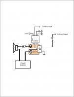
In the way I am planning to do it is by connecting the amplifier output to a solid state relay to the speaker then the speaker ground through a 1 ohm resistor to ground. By checking the voltage at the resistor I can determined the current. The problem I have is what to do next. Do I calculate the current base on the amplifier max. watts to disable the relay or determine by the max. current that the output transistors can handle? what to do ??????. This is the question.
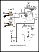
Attached It is the schematic I am using right now.
I think that 1 Ohm is way too big.
Regarding what to do next, it doesn't have to be just one thing. Power and current limits could both be checked.
Maybe the resistor should be at the amplifier output, before the speaker. Then you could also measure the output voltage and use a multiplication to calculate the instantaneous output power level. (It would come out about the same, either way, maybe.)
Output voltage could be continuously averaged, over the last XX ms, to check for severe DC offset problem. Not sure if it would be able to be fast-enough. But if you can't save the speakers maybe you could still prevent a fire.
Your 7-count test does need to be upgraded, dramatically, I believe.
Normally when the music is playing the max count goes is 2. I test the count in the bench using a variable resistor to simulate the speaker output and you have to keep it moving because it will disable the relay fast. I like to test it in my amplifier but my neighbor already called the police and they give me warning. NO LOUD MUSIC. I may have to test it with a big dummy resistor.
If we put the resistor at the output of the amplifier then I will need 2 I/O per channel and also I can read the voltage and the current. Calculate the voltage and the current to use it to enable/disable the relay. I am going to built the solid state relay and test it using a transistor with 40 volts and short the output and see what it is smoke. I need to order some parts.
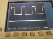
Finally I received the parts to build the solid state relay and built an S.S.R. prototype. This is my first experienced with mosfet transistors. I built the prototype using some spare Mosfet IRF640 250 volts 18 amps. Right now the only thing I am doing is it closing and open the relay using a PS 50 volts 4 amps. For the test I am using a transistor 2N3055 to drive the load of a 400 ohm resistor and an 8 ohms dummy resistor. This is the first step. The second step is to write a program to read a resistor voltage drop to calculate the current and open the relay. I am planning raise the voltage to 72 volts then short the 400 ohms to see if the micro can open the relay on time before the 2N3055 goes out. Attached is a scope picture of the relay switching off and on. Tomorrow I will start the programming to read the voltage drop.
Attachments
Test the prototype solid state relay in my amplifier and noticed no sound degradation or distortion. Test it with a sine wave and also no wave distortion was noticed. Next step it is to read the output current using the linear ACS712 current sensor. I was going to do it reading the voltage drop to a resistor but the voltage was too low and require an op amp. By searching the web I found the ACS712. The output voltage it is a linear proportional to the current. I am planning to install it as part of the solid state relay.
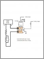
Attached it the design drawing.
Attached it the design drawing.
Attachments
Finally the ACS712-20 amps Hall effect current sensor arrived today. I built a jig to test it using a 70 volts 4 amps power supply with two resistors and a switch to bypass one of the resistors when an increase in current it is require. Programmed the micro to monitor the current sensor and turn off the SSR if the current reached the 2.00 amps or higher. Also to test under load I used my SSR as part of the test since it will be part of the final project.
Some members requested the test to see the feasibility of monitoring the current to protect the speaker from high voltage. This is a big problem with high power direct output couple amplifiers.
The purpose of the test it is to simulate a failure of the amplifier output transistors and see if it is possible to disconnect the speakers by monitoring the current before they are destroy by the high rails voltage. This will be accomplished by shorting the resistor to simulate an amplifier output transistors failure. This will increase the current to a point that supposedly should burn the speaker but by the used of the micro this will be prevented.
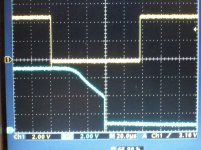
Attached is the scope picture showing the test resulted. The top signal it is the SSR enable signal and the bottom it is the signal of the 70 volts coming out of the SSR to the load, High signal means that the SSR it is enable and a zero means it is disable. The micro will monitor the current and when it reached a limit of 2 amps the micro will disable the SSR by sending a 0 volts to the SSR.
As you can see it took 60 usec for the output voltage to go from 70 volts to zero volts after the micro disable the SSR. This delay it is due to the Avago photovoltaic mosfet driver turn off time. This test proved that it is possible to protect the speaker from a total amplifier output transistor failure by monitoring the speaker current.
Up to now these are the functions that the micro can perform to protect the speakers.
1- Delay on power ON
2- Mute
3- Enable the speaker before checking the output to be within specifications < .5 volts
4- Protect the speaker from constant high current/high voltage
5- Monitoring constantly the speaker current
6- Disable the speaker/mute it in power OFF by monitoring the rail voltage
7- Clipping
8- Solid state relay to enable the speakers
I will do some more tests to make sure that the speakers can be protected from an output short. This will completed all the test need it to finalized the final design.
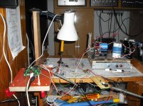
Also attached is the test jig schematic and a picture of my test area.
Also by the test means that by monitoring the current is the only thing need to protect the speakers. The other checks are not necessary but by using the micro this can be easily done.
Some members requested the test to see the feasibility of monitoring the current to protect the speaker from high voltage. This is a big problem with high power direct output couple amplifiers.
The purpose of the test it is to simulate a failure of the amplifier output transistors and see if it is possible to disconnect the speakers by monitoring the current before they are destroy by the high rails voltage. This will be accomplished by shorting the resistor to simulate an amplifier output transistors failure. This will increase the current to a point that supposedly should burn the speaker but by the used of the micro this will be prevented.
Attached is the scope picture showing the test resulted. The top signal it is the SSR enable signal and the bottom it is the signal of the 70 volts coming out of the SSR to the load, High signal means that the SSR it is enable and a zero means it is disable. The micro will monitor the current and when it reached a limit of 2 amps the micro will disable the SSR by sending a 0 volts to the SSR.
As you can see it took 60 usec for the output voltage to go from 70 volts to zero volts after the micro disable the SSR. This delay it is due to the Avago photovoltaic mosfet driver turn off time. This test proved that it is possible to protect the speaker from a total amplifier output transistor failure by monitoring the speaker current.
Up to now these are the functions that the micro can perform to protect the speakers.
1- Delay on power ON
2- Mute
3- Enable the speaker before checking the output to be within specifications < .5 volts
4- Protect the speaker from constant high current/high voltage
5- Monitoring constantly the speaker current
6- Disable the speaker/mute it in power OFF by monitoring the rail voltage
7- Clipping
8- Solid state relay to enable the speakers
I will do some more tests to make sure that the speakers can be protected from an output short. This will completed all the test need it to finalized the final design.
Also attached is the test jig schematic and a picture of my test area.
Also by the test means that by monitoring the current is the only thing need to protect the speakers. The other checks are not necessary but by using the micro this can be easily done.
Attachments
Interesting thread. Maybe I missed it, and if so apologies, but did anybody post a schematic of the SS relay with the MOSFETs?
jan didden
Do you mean this one ?
http://www.diyaudio.com/forums/solid-state/191449-output-relays.html
Yes,
http://www.diyaudio.com/forums/solid-state/191449-output-relays-2.html#post2618977
and real scope tests,
http://www.diyaudio.com/forums/solid-state/191449-output-relays-13.html#post2659578
Jan... it's worth reading all the thread... some really interesting info buried in there.
http://www.diyaudio.com/forums/solid-state/191449-output-relays-2.html#post2618977
and real scope tests,
http://www.diyaudio.com/forums/solid-state/191449-output-relays-13.html#post2659578
Jan... it's worth reading all the thread... some really interesting info buried in there.
Ahh yes, thanks!
jan
Ahh yes, thanks!
jan
Lol... in case you missed the quick edit above... read it all
")
Will do. What I would be interested in is the realy closed, with an output voltage on the load say 20VRMS and then put the scope or better a spectrum analyzer across the relay. That should provide a good idea of the quality; hopefully the residual should have the same harmonics as the main signal indicating a linear Rdson.
jan
jan
I would like to recommend for those members that are looking on how to protect the speaker that you do not need a micro to use the ACS712-20 amps sensor. This sensor used the hall effects to read the current and convert it to volts. The output is proportional linear to the current. Zero it is 2.5 volts and 20 amps it is 4.5 volts. Also it can read negative amps from 2.5 to .5. The span it is 2 volts up/down. This means that you can use a comparator to set the limits where you want to turn off the speaker output. You can set one when the output is positive and another when it is negative. So you can protect the speaker using the output current to protect the speaker.
Will do. What I would be interested in is the realy closed, with an output voltage on the load say 20VRMS and then put the scope or better a spectrum analyzer across the relay. That should provide a good idea of the quality; hopefully the residual should have the same harmonics as the main signal indicating a linear Rdson.
jan
Hello Jan,
SSR based on mosfets are very linear once turned fully on - the variation of Rdson with current is extremely low. Figures of circa 1ppm have been measured with an AP and put up on the site - 100V Vds and 4.8mO devices - but sorry, I do not recall the guys name (it's in the output relay thread from about 10 days ago).
Simulation gives the same result too BTW.
Last edited:
I did some limited test by using a sine wave generator and injected a millivolts signal to the SSR and I didn't see any degradation in the output sound. Also connected it to my amplifier output and check to see any difference in sound by comparing both speakers sound. No differences in sound I was able to noticed . Right now I am in the final stage of my design and I am looking in which mosfet to use. I am using in my test the IRF640 200volts 18 amps 0.18 ohms. I need to make a decision in which to use. I need one that can be use for almost all amplifiers. I was looking for one of 250 volts and at least 50 amps. Yesterday finally I decided to short the wires and when I did it there was a big sparked in the wires and the micro did the job. The PS fuse didn't see it. It is surprised me how good it is worked. I did it 2 to 3 times with the same results. Also I am not decided if only used the output current to check the output. Leave out the DC rails checks. This will simplified the circuit. Checking only the current will eliminated a lots of components and will be just a simple circuit. Using the Allegro hall effect current sensor I can up to 100 amps. That it is a lots of current. Right now I am using the 20 amps current sensor.
Right now I am in the final stage design of the project. Due to the good results of the current checking I am making the decision to design the output protection using only the current output. By checking the status of the current output I can determined the output health of the amplifier and it will let me to make a decision on disable or not the SSR to the speaker. I will used only the positive rail voltage to mute / disable the speaker output SSR when the amplifier if powered up/down. All other test are unnecessary in my opinion. Since the sensor can read +/- current it will allow me to check both +/- rails failures and disable the speaker output.
Please those that are following this tread your advices and recommendations are welcome for anything that I am missing out.
Attached is the final schematic.
Please those that are following this tread your advices and recommendations are welcome for anything that I am missing out.
Attached is the final schematic.
Attachments
- Status
- This old topic is closed. If you want to reopen this topic, contact a moderator using the "Report Post" button.
- Home
- Amplifiers
- Chip Amps
- Protecting the speaker output using a microprocessor