Interesting. Right now I'm working on making the disparate ideas I already have on my plate play nice with each other. I'm not really concerned at this point in refining current balance with a microprocessor. Provisions are already made for individual manual bias control for each tube via a dedicated source follower mosfet. Overall balance of each side of the push-pull for each channel will be front panel accessible without changing each tube's individual bias adjustment. Two meters on the front for that. I'm old school that way. I'm also a believer that when you explore new territory then it behooves you to be as conservative as possible in every other aspect.
Despite my own preferences I hope you can get it to work reliably for you. I'm sure there are many members here that would be interested in what you are doing.
I am only monitoring the current through each tube with this. I have a pot to adjust bias for each tube using fixed bias. This is designed to hopefully catch a runaway tube or bias failure. It also can be programmed as a delayed start and has soft start by way of the two relays and a CL-80 thermistor (47 ohm inrush current limiter)
It works well looking for a 20% imbalance. I will see how much I can cut that down without generating a false shut down. Right now it waits until one of the tubes reaches 90% of operating current when the amp is turned on before it starts to monitor the tubes.
This will not supress the spark in a sudden completely but reduce to a harmless level before cutting the circuit off .
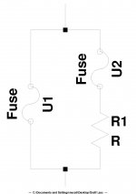
F1= desired cut off current
F2= 1/2 F1
R= slightly lower than B/F1
F1 cuts off. Current ( so the spark ) is limited to a lower value by R.
F2 cuts off .
Simple and, i think, reliable.
F1= desired cut off current
F2= 1/2 F1
R= slightly lower than B/F1
F1 cuts off. Current ( so the spark ) is limited to a lower value by R.
F2 cuts off .
Simple and, i think, reliable.
Attachments

GDTs look to be very promising. I think I will buy one rated for 240VAC and put it across one of the primaries on my Plitron amp. That one doesn't normally have very high voltages on either of the primaries, since it is a 50% CFB design.
It would be simple to do a before and after distortion measurement at large signals to make sure I'm not reducing the fidelity of the amp.
It would also be nice to see some testing of them getting punished if George ever gets around to it.
It would be simple to do a before and after distortion measurement at large signals to make sure I'm not reducing the fidelity of the amp.
It would also be nice to see some testing of them getting punished if George ever gets around to it.
Tim,
My computer with the LTspice schematic died. I use screen save function to post a schematic here, so can't do it.
It's 335 volts on primary, approx 80 milliamps on each side of primary. 600 pf of primary capacitance. Don't know on secondary. 2k ohms impedance on primary using 5 ohm speaker model. It will be driven ab2 with individual mosfet followers per tube with only 10% cathode feedback from the OPT in the cathodes. That seems like it should be enough for you to work with.
I think I'll probably go with George's idea of GDTs across primary unless you have a compelling reason not to.
Can you link to a similar circuit schematic/configuration?
Is 600pf an external part?
Is there a feedback winding loading the secondary?
In general, a MOV can be achieved using series parts to give a suitable designed value of 1mA conduction, below which the MOV has effectively no influence. GDT's are much less common to purchase with a good range of values, and may not be available for the voltage you want to design conduction for.
In general, a MOV softly clips, so may not be noticeable for the odd time that it starts to become conductive, and instantly has no influence after the over-voltage event. A GDT would be expected to have a noticeable influence until conditions cause the conduction to cease.
There was some comment earlier on MOV capacitance - a part's capacitance is somewhat proportional to disk size (Joule rating), and inversely proportional to voltage rating. Higher voltage MOV's (as per in common use for 240VAC application) in a smaller format (eg. 5-10mm disk diameter) have pretty much negligible capacitance even if you were concerned with 100kHz+ influence, especially as the MOV is usually a series connection of 2-3 MOVs (and hence capacitance is 1/2 or 1/3).
The OPT may have a nominal insulation voltage rating, or have passed a test at a particular voltage. Ask the manufacturer. That indicates the upper limit that you may want any over-voltage protection to kick in (so you don't stress the insulation more than what the manufacturer tests or designs to). That usually means the protective device can have a wide range within which it is being asked to perform - obviously better to keep the operating level of the OVP to be as high as possible (which is usually far in excess of normal class A swings).
Tim
Last edited:
Rob did a 2100 CFB/H based amplifier. Worth a look to see some of his design choices.
Motional feedback intro
I noted it as I have the same Plitron Power and Output Tranny set on my shelf waiting.
Cheers,
Ian
Motional feedback intro
I noted it as I have the same Plitron Power and Output Tranny set on my shelf waiting.
Cheers,
Ian
gingertube,
Just finished reading Rob's article. An interesting read. I originally got interested in my own project from owning a hifi amp that just sounded terrific to my ears but measured horribly for distortion in the hifi magazine reviews. This was years and years before I was interested in tube electronics. Unfortunately it was unstable due to some cheap design decisions by the manufacturer and it autodestructed over a period of years. If it hadn't I would be happily listening to it today and feeling no need to know what's over the horizon in other amplifiers.
A good deal of the satisfaction from that amp was the ability to tune it to my listening requirements. You could change the global feedback and I found over a period of time that about 3db of gb was all that was needed under all conditions. Anything more and I'm sure it would have measured much more but sounded worse. I can verify the sounding worse part.
The other thing I liked about it was that it had six small output tubes per channel push pull. Ordinarily that would seem like a big waste and uneconomic rather than using 2 largish output tubes for the same power. But what it had going for it was that you individually select output pairs in triode or pentode modes. It really makes a difference in the sound to be able to do that. Most people just take it for granted that that particular sound characteristic is either salt or pepper. It doesn't have to be. The current going through each side of the primary just add arithmetically in the windings, just like all parallel currents do. There's nothing inherently euphonic or "instrument amp" like in its characteristics when you find a middle ground between triode and pentode. I don't see it as choosing to make an amp distort purposely unless any decision to use triode or pentode topology is a decision how to purposely distort. A better way to say it is that this kind of thing should not be put in category of instrument amp distortion because it is not a dynamic distortion which is what instrument amp controls center around.
So that's what I'm trying to recreate from that old amp but with a much better implementation. Hence, the individual mosfet source followers driving each tube. Each tube pair will be able to be selected triode or pentode. Since I needed so little gf in the original amp I'm going to see if the cathode feedback will replace it. It might not totally. We'll see. Also, that original amp used 12ax7s with lots of local feedback. Looking at the schematic of that amp it seems like a tremendous waste. So I'm going with a single voltage gain/inverter stage using one dual 6sn7 driver/cathodyne. It eliminates big output valves as an option because there just isn't enough driving voltage to supply them. But my particular case doesn't need them because this topology trades that for the higher gm in multiple out tubes. I also found that driving 4 tubes in push pull using ab2 supplied drive provides more output power than 6 tubes without that. A further simplification.
It could well be that there was a kind of distortion designed into that previous amp that made it sound the way I remember. I hope not. I'm hoping that designing this amp for as low a distortion as possible (without gf) will make it sound equally good. If not I have provided one failsafe modification: I can select to add two different resistances onto one of the split loads in the cathodyne circuit to unbalance it. Under simulation that provides approximately 1.5% or 3% 2nd harmonic distortion to the mix.
Last edited:
gabdx,
The point of describing my own journey wasn't to praise excess complication. It was only by pure accident I found that there are topologies that do not fit into standard arrangements that sound really good. One does not always encounter them even in a forum such as this, unless you experiment. If you would like to stick to the tried and true only, then that's fine. YMMV. You may not have understood, but the whole point of my project is to simplify the circuit as much as possible and still have the ability to change parameters to shape the sound. In other words, to try to minimize the risk in a project of this sort while simultaneously attempting that. You are not seeing that.
The point of describing my own journey wasn't to praise excess complication. It was only by pure accident I found that there are topologies that do not fit into standard arrangements that sound really good. One does not always encounter them even in a forum such as this, unless you experiment. If you would like to stick to the tried and true only, then that's fine. YMMV. You may not have understood, but the whole point of my project is to simplify the circuit as much as possible and still have the ability to change parameters to shape the sound. In other words, to try to minimize the risk in a project of this sort while simultaneously attempting that. You are not seeing that.
I've been thinking about this thread. Sometimes I just need to write things down, like I did in comment #30, just so I can roll the idea around in my head. After much thought I've decided it will be a little reckless to put my somewhat fragile Plitron in an admittedly experimental circuit. I think I will implement the circuit I described in stages with the 6sn7 driver/cathodyne the first change. I'll be including a switchable cathodyne unbalancer. (Don't worry, it won't interrupt the current path, but just add a switchable resistance or two in parallel with the cathode end of the split load.)
Initially I'm just going to use cathode autobias for the output tubes like the original circuit I'm emulating. Not because it's the best biasing , but because it will help to mind the store in case of a runaway tube. If everything works out and I like the sound then Ill go for more changes incrementally- first the source followers in ab2. If everything works good, the sound is still good, and I have high confidence in its reliability then I "might" substitute the Plitron. It's just too expensive an OT to take needless risks with it.
BTW, the downfall of the original circuit was not the OT, but the PT. It had to do with it being underspecified and replacement tubes that drew too much current for the power transformer to handle. In fact, I'll be using the original OTs from that amp for this build because they still seem to be in good working order.
Last edited:
I've been thinking about this thread. Sometimes I just need to write things down, like I did in comment #30, just so I can roll the idea around in my head. After much thought I've decided it will be a little reckless to put my somewhat fragile Plitron in an admittedly experimental circuit. I think I will implement the circuit I described in stages with the 6sn7 driver/cathodyne the first change. I'll be including a switchable cathodyne unbalancer. (Don't worry, it won't interrupt the current path, but just add a switchable resistance or two in parallel with the cathode end of the split load.)
I implemented an adjustable imbalance in the phase splitter in my amp. I put a trimmer pot in plate loads of the LTP input stage.
My Fisher amp has something similar in their cathodyne splitters. They just put a trimmer pot in one of the loads so that it could be adjusted to +-10% or so of the "balanced" resistance. I think that the idea was to have an adjustment to account for mismatch in gain from the two output tubes and use it to minimize overall distortion. Most designs don't go to the effort to minimize distortion this way.
I thought it was fun to try different levels of even harmonics and see what difference it made to the sound. Ultimately, I set it to minimize them but it was an interesting experiment. The setting to minimize distortion was not the same as the setting to produce perfect phase splitter balance.
Yes, one can go a lot farther to balance the phase inverter than most manufacturers ever go. I'm glad to see I'm not the only one who has or will be experimenting with that. The paraphrase inverters don't appeal to me because its kind of like those spooky movies where someone is looking in the mirror and the mirror image isn't always mirroring what's going on in the original movement of the person. Yikes!
The cathodyne definitely has the best potential balance of any of the inverters. It also doesn't depend on anything but the passive resistors. I suppose if one really wanted to over obsess then you could do what Morgan Jones recommends and heat the wire wound load resistors to a very moderate temp in the oven and then let all the stresses that would usually be relieved over years happen in an hour or so. Then just pick the best resistor matches among a dozen or so. They should be stable and very well matched after that.
That potential perfect inversion is one of the biggest reason for me to want to use a single stage driver. Why use the perfect phase splitter only to then put each phase through separate amplifying devices where there is the potential to mess it up again.
Also, when I simulated the cathodyne circuit in LTspice I noticed something important. If you do not bias the cathode of it at 1/4 of the total voltage for the cathodyne then you start getting upper harmonic distortions. Especially at higher signal levels. It seems to be happening because the upper and lower loads must be equally split "within" that valve. If I tried to do it like the orginal implementation, i.e. direct coupled in the Williamson, I couldn't get the second tube to bias at that optimum point. So I've used Sy's biasing method in his impasse preamp to get there. It shows significantly better results in the FFT measurement than anything direct coupled between the driver and cathodyne. So it seems the Williamson isn't perfect, despite rumors to the contrary.

Raise the voltage of the cathodyne supply - that would raise the 1/4 bias level.
To assist appreciation of the total signal chain, can you indicate what signal swing is required at the cathodyne to achieve full output of the amp, and relate that to the achievable cathodyne swing?
To assist appreciation of the total signal chain, can you indicate what signal swing is required at the cathodyne to achieve full output of the amp, and relate that to the achievable cathodyne swing?
Last edited:
That potential perfect inversion is one of the biggest reason for me to want to use a single stage driver. Why use the perfect phase splitter only to then put each phase through separate amplifying devices where there is the potential to mess it up again.
Well, the point I was trying to make was that obsessing over perfect phase splitting/inversion is only useful if gain is perfectly balanced in all stages after the phase splitter. If there is any imbalance in gain after that point, (there almost always will be) making the balance perfect didn't buy you anything except maybe a small increase in statistical likelihood of less distortion.
You are better off (distortion-wise) making a phase splitter that you can use to fine tune imbalance to attempt to cancel out the imbalance in the subsequent stages while looking at a distortion spectrum.
Then, if you want to play around with adding some imbalance to generate even harmonics, you can do that too. Of course, any feedback loop around the phase splitter will tend to fight that imbalance. I don't have feedback around the phase splitter in the amp I did this with.
Tim,
My understanding is that the max signal out of a cathodyne is ultimately controlled by the max B+ the tube can take. Using a 6sn7 as an example, it can take 450 volts. A secondary consideration is the heater cathode breakdown voltage. So for a 6sn7 you have to bias the cathode at 112.5 volts. Then the ultimate theoretical output signal would 225 volts p-p on both upper and lower loads. But using LTspice it says you can't get there. That makes sense because you can't go all the way to zero on the cathode load, and you can't get all the way to 450v on the plate. Also, if either signal attempts to broach the 225 volt level on either load from either direction it will bump into the requirements of the opposite load and will heavily distort. In my simulation the max output was 99volts peak or 198v p-p. So that works out to about 80% of the theoretical limit of 225 volts, a limit which is never achieved in real life.
My understanding is that the max signal out of a cathodyne is ultimately controlled by the max B+ the tube can take. Using a 6sn7 as an example, it can take 450 volts. A secondary consideration is the heater cathode breakdown voltage. So for a 6sn7 you have to bias the cathode at 112.5 volts. Then the ultimate theoretical output signal would 225 volts p-p on both upper and lower loads. But using LTspice it says you can't get there. That makes sense because you can't go all the way to zero on the cathode load, and you can't get all the way to 450v on the plate. Also, if either signal attempts to broach the 225 volt level on either load from either direction it will bump into the requirements of the opposite load and will heavily distort. In my simulation the max output was 99volts peak or 198v p-p. So that works out to about 80% of the theoretical limit of 225 volts, a limit which is never achieved in real life.
Last edited:
Well, the point I was trying to make was that obsessing over perfect phase splitting/inversion is only useful if gain is perfectly balanced in all stages after the phase splitter. If there is any imbalance in gain after that point, (there almost always will be) making the balance perfect didn't buy you anything except maybe a small increase in statistical likelihood of less distortion.
You are better off (distortion-wise) making a phase splitter that you can use to fine tune imbalance to attempt to cancel out the imbalance in the subsequent stages while looking at a distortion spectrum.
Then, if you want to play around with adding some imbalance to generate even harmonics, you can do that too. Of course, any feedback loop around the phase splitter will tend to fight that imbalance. I don't have feedback around the phase splitter in the amp I did this with.
That's a really good point. I hadn't actually thought of that, but I will now.
But that would imply that you are designing your amp's input signal to drive the cathodyne to its swing limits - which I would estimate is far from a practical situation in the W.
On the other matter of balanced operation through the stages - the original W had a balancing pot included in the driver supply path. I guess that having resistors matched to better than 1% would see a minimum THD level with a little tube rolling of the driver - given that the cathodyne has in-built balancing.
On the other matter of balanced operation through the stages - the original W had a balancing pot included in the driver supply path. I guess that having resistors matched to better than 1% would see a minimum THD level with a little tube rolling of the driver - given that the cathodyne has in-built balancing.
- Status
- This old topic is closed. If you want to reopen this topic, contact a moderator using the "Report Post" button.
- Home
- Amplifiers
- Tubes / Valves
- Protecting Plitron OPT