Actually, I may be wrong about that 198 volt p-p. I seem to remember it being 99 volts p-p. Unfortunately my spice simulation died with the computer so I can't say if my memory is playing tricks on me. Maybe someone else can check if I'm off by a factor of 2.
Edit. I think I remember why now. The mu of the 6sn7 is 20 and I was using a 2 volt rms signal as a standard input to the driver. You can use a higher signal level input than that. It seems to have been a coincidence that the two number coincide by a factor of 2. Unfortunately the signal starts distorting at higher output levels. But that's just to be expected. It's really really low distortion for the higher harmonics even at 99 volts p-p. And it'll go twice that high but with increasing distortion. But that sure isn't news to anyone here.
Edit. I think I remember why now. The mu of the 6sn7 is 20 and I was using a 2 volt rms signal as a standard input to the driver. You can use a higher signal level input than that. It seems to have been a coincidence that the two number coincide by a factor of 2. Unfortunately the signal starts distorting at higher output levels. But that's just to be expected. It's really really low distortion for the higher harmonics even at 99 volts p-p. And it'll go twice that high but with increasing distortion. But that sure isn't news to anyone here.
Last edited:
To make a long confusing story much simpler - the difference between the 112 volts p-p I expected with mu of 20 and the the 99 volt p-p output signal I actually got didn't have to do with limitations at the halfway point of 225 volts. It just has to do with the fact that the cathodyne loads aren't infinite so it isn't a perfect follower and does not actually have a gain of 1.
I hope I haven't completely confused everyone out there. The 225 volt limitation is real but that is another issue entirely. Sorry bout that.
I hope I haven't completely confused everyone out there. The 225 volt limitation is real but that is another issue entirely. Sorry bout that.
With the W, the signal level at the cathodyne, for full amp output, is I recall pretty small compared to the available swing from the cathodyne - even if cathodyne was not set up optimally for largest dynamic swing.
Miller in 1961 proposed changes to increase the dynamic range of the early W stages, and indicated an improvement in IM%. The first stage bias was increased from 2.1 to 3V. The cathodyne stage supply voltage was increased, which moved the apportionment to a better 1/4, 1/2, 1/4. And the driver stage had its bias voltage increased from 4.5 to 8.5V.
The theoretical gain of the W cathodyne is 0.89.
Last edited:
Here is my cathodyne at slightly less than the 1/4 split. It drives the KT120's well into clipping. The grid chokes do help and also I am not using any feedback around the cathodyne. Running the KT120's as triodes I get 40 watts which is lots of power. This is my favorite amp ever for sound.
Any modern CD/DVD player with 2v output will drive it nicely. The 6CG7 gave the lowest distortion...12AU7 the worst.
Any modern CD/DVD player with 2v output will drive it nicely. The 6CG7 gave the lowest distortion...12AU7 the worst.
Attachments
Here is my cathodyne at slightly less than the 1/4 split. It drives the KT120's well into clipping. The grid chokes do help and also I am not using any feedback around the cathodyne. Running the KT120's as triodes I get 40 watts which is lots of power. This is my favorite amp ever for sound.
Any modern CD/DVD player with 2v output will drive it nicely. The 6CG7 gave the lowest distortion...12AU7 the worst.
That looks like a really nice implementation. I'm inclined to borrow ideas from it and scrap using one tube for amplification and phase splitting in a dual tube. I like the idea of using a 12ax7 paralleled too. It's a little more gain than I need but I may use some local feedback (unbypassed cathode) to tame it. It at least gives me enough gain to drive 6v6s to clipping which the 6sn7 couldn't do. I then have the option of ppp 6v6s as well as el84s.
Something I noticed - you have a lot of volts on that 6cg7 but it's only rated at 300 volts plate voltage. Are you worried about flashover before the heaters warm up? Also, what's C1 for?
Something I noticed - you have a lot of volts on that 6cg7 but it's only rated at 300 volts plate voltage. Are you worried about flashover before the heaters warm up?
That 300V rating should be just the max quiescent Va-k. He's running Va-k = 272V so it looks fine to me.
That 300V rating should be just the max quiescent Va-k. He's running Va-k = 272V so it looks fine to me.
I was thinking more about before the load resistors pass current and before they drop voltage. For instance, when there exists B+ but heaters haven't warmed yet and the tube isn't conducting. But if he hasn't had problems yet then perhaps he won't.
I was thinking more about before the load resistors pass current and before they drop voltage. For instance, when there exists B+ but heaters haven't warmed yet and the tube isn't conducting. But if he hasn't had problems yet then perhaps he won't.
That's what I'm saying, a design-center DC plate voltage maximum rating takes into account that there will be momentary plate voltages well in excess of this number. I would say that you would be fine up to at least twice this value for momentary plate voltages.
Hi exeric:
No problems with the 6CG7 the amplifier has been running daily for over a year and I expect many more years of service from the 6CG7. Also with the relatively large cathode resistor as soon as any current flows the voltage on the cathode of the 6CG7 goes up. 6CG7 has a 200v rating for Heater negative with respect to cathode also and I don't think I ever exceed that in this design although you could elevate the heater winding if you wanted to. The small C1 cap is to stop any oscillation in that stage. I have not tried it without C1. I found the grid resistors on the KT120 are required without them the amplifier would oscillate like crazy as soon as you put a signal through it. Cheers!
No problems with the 6CG7 the amplifier has been running daily for over a year and I expect many more years of service from the 6CG7. Also with the relatively large cathode resistor as soon as any current flows the voltage on the cathode of the 6CG7 goes up. 6CG7 has a 200v rating for Heater negative with respect to cathode also and I don't think I ever exceed that in this design although you could elevate the heater winding if you wanted to. The small C1 cap is to stop any oscillation in that stage. I have not tried it without C1. I found the grid resistors on the KT120 are required without them the amplifier would oscillate like crazy as soon as you put a signal through it. Cheers!
I have a design that routinely feeds about 500 volts to the 6GC7's on start up and runs them near 300 volts. Its been kicked around from test amp to test amp for nearly 7 years. There is also a 6SN7 version that's been around as long. Both boards still have the original previously used tubes in them. They go back to the 6L6GC in AB2 thread. The latest version does about 100 V P-P per phase at 0.14% distortion with zero feedback. It can make about 200 V P-P without clipping from a 500 volt supply. With mosfet buffers, it can drive the grids right out of most tubes.
http://www.diyaudio.com/forums/tubes-valves/133034-6l6gc-ab2-amp.html
The neon bulb is a clamping device to prevent H-K failures on start up with high negative supply voltages. Some big tubes like the 845 need -200 volts.
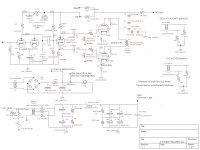
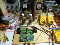
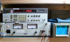
The driver schematic is enclosed, as are a pair of pictures showing 202 watts being shoved through one of my Plitrons by a pair of 4D32 transmitting tubes on 650 volts.....yes that is running a wee bit over 300 volts on the 6CG7's. More like 400 volts idle, 470 on signal peaks. The 6CG7 is derived from the 6SN7 which was used in TV sweep oscillators. The "peak positive plate voltage" is specced at 1500 volts.
http://www.diyaudio.com/forums/tubes-valves/133034-6l6gc-ab2-amp.html
The neon bulb is a clamping device to prevent H-K failures on start up with high negative supply voltages. Some big tubes like the 845 need -200 volts.
The driver schematic is enclosed, as are a pair of pictures showing 202 watts being shoved through one of my Plitrons by a pair of 4D32 transmitting tubes on 650 volts.....yes that is running a wee bit over 300 volts on the 6CG7's. More like 400 volts idle, 470 on signal peaks. The 6CG7 is derived from the 6SN7 which was used in TV sweep oscillators. The "peak positive plate voltage" is specced at 1500 volts.
Attachments
I've read through most of the 6L6 thread. But where I was most impressed about the virtues of ab2 was your website, Tubelab. That's also where I read that it didn't have to involve a lot of excess complication and heat if you just used mosfets instead of tubes. Kudos to you! The ultimate goal is to use mosfets and ab2 to drive the finals. It also allows a (somewhat) economical way to drive parallel output tubes independently. Something important in my situation.
But I'm the kind of person that borrows good ideas independent of the individual. If an individual has a great idea today I'll use it non-commercially and openly give credit to the party that invented it. But I'm loyal to the idea, more than the person. That's why I've recently gotten loyal to the split load inverter. I think Morgan Jones gave it pretty short shrift in his books. A lot less than it deserves. I think he was thinking only in terms of the implementation that was used in the W. That was a pretty restricted example and not the best use of it, in my opinion.
I've come to think that the best use of it is right before the finals in a push pull circuit. If you use it that way then you have the least chance of messing with perfect balance between inverted and non-inverted inputs going to the final. Of course that means all voltage gain needs to be done before the cathodyne. But that seems to me a much simpler arrangement than in the W and easily doable.
It was always recommended to use grid and anode stoppers. Did you want to not use them for a reason?Hi exeric:
I found the grid resistors on the KT120 are required without them the amplifier would oscillate like crazy as soon as you put a signal through it.
Did you note how many tubes you rolled through your testing, and what the THD% magnitude spread was with the samples, and whether the THD% characteristic was at both low level and when output stage assymetry may be starting to impose? How well were the R4/R5 matched?The 6CG7 gave the lowest distortion...12AU7 the worst.
Last edited:
- Status
- This old topic is closed. If you want to reopen this topic, contact a moderator using the "Report Post" button.
- Home
- Amplifiers
- Tubes / Valves
- Protecting Plitron OPT