KaDe said:Okay, when the 620R is shorted you will have grid-bias like in the Grommes 260A.
This 12AU7 cascode gives very vivid sound.
I haven't found the 6SN7 to be a stellar performer at currents much less than 5mA. The steep load line the cascode imposes on the lower triode can't help linearity and I am not a fan of grid leak bias under any circumstance where significant signal levels are present. (Although arguably this might be acceptable in a common grid stage. Still more bias is needed.)
KaDe said:Okay, when the 620R is shorted you will have grid-bias like in the Grommes 260A.
This 12AU7 cascode gives very vivid sound.
This high fidelity Grommes looks like a very good candidate to a nice guitar amp.

Hint: what kind of volt/ampere curve has a triode when it's anode voltage is kept constant?
kevinkr said:6DJ8 comes immediately to mind..
If you can tolerate non-linearity and microphonics, sure.
Constant current Mu loading and/or good local feedback
scheme, plus some physical isolation or damping. This
should still make a very viable tube for audio.
Sure hope I am not mistaken. I must got like 50 of em.
As they came from my father, I want to use them.
y=x^1.5Wavebourn said:what kind of volt/ampere curve has a triode when it's anode voltage is kept constant?
Mu (constant plate current) is quite linear, even for poor triodes
with very badly bent curves that lean grossly over to the right.
Transconductance (constant plate voltage) is simply never linear.
Not even for the best triodes. You simply don't want to go there
without feedback.
kenpeter said:
y=x^1.5
So, pros:
1. Good intermodulator
2. Wide frequency bandwidth.
Cons:
1. Good intermodulator
2. Low output swing
Good: for UHF mixing, bad: for audio amplification
Wavebourn said:
So, cons:
1. Good intermodulator
2. Wide frequency bandwidth.
For simple cascode gone "full-retard", thats about how it scores.
I've given example on the previous page, of a hybrid topology
with ultralinear feedback, and far fewer problems.
I'd probably not bother with the cascode. Just disconnect the top section by removing the 620R, then use a plate resistor or outrigger CCS from the bottom section to B+. You want a high mu there, maybe a 6SL7. The other problems with this design remain- there's not even close to enough open loop gain to make the feedback effective. Me, I'd get an Xacto knife and do some trace surgery and put a FET on the bottom and a 6SL7 on top, but that is not a job for the faint-hearted.
Another alternative for the brave is a starved-current cascode with a very high plate resistor (perhaps that what this designer was aiming for, but didn't pull off correctly). That will take a lot of bench experimentation. I'll try to dig up the version I tried and post it (though perhaps I already have); it could be adapted to a 6SL7 if memory serves. How are the sections divided, i.e., are the bottom and top of the cascode a separate tube from the phase splitter?
Another alternative for the brave is a starved-current cascode with a very high plate resistor (perhaps that what this designer was aiming for, but didn't pull off correctly). That will take a lot of bench experimentation. I'll try to dig up the version I tried and post it (though perhaps I already have); it could be adapted to a 6SL7 if memory serves. How are the sections divided, i.e., are the bottom and top of the cascode a separate tube from the phase splitter?
How about simply requesting to return this board for a refund?
It seems like the first question I would ask under the circumstances.
A full refund to any dissatisfied customer who purchased my boards was always a part of my business strategy - hopefully this seller will do the same. I suspect this was not a particularly cheap board either. (Note: My boards are no longer available.)
Be diplomatic if at all possible. Hopefully there is no restocking fee, and a seller who stands behind his product.
Sy, whats the theory of operation on that last circuit you posted?
120R for grid leak seems awful small. All the values seem a bit
out of whack, but then again you said it was starved. Maybe its
intentional to be that way? I just can't put 2 and 2 together and
figure how this works to make a cascode any better behaved?
120R for grid leak seems awful small. All the values seem a bit
out of whack, but then again you said it was starved. Maybe its
intentional to be that way? I just can't put 2 and 2 together and
figure how this works to make a cascode any better behaved?
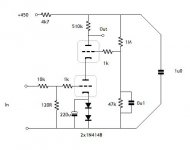
The large input resistor and small grid leak were used as an input attenuator for test purposes- the gain is so high (51dB) that with usual input levels, the output saturates. In real-world use, you'd have a more normal 100k or so grid leak and no input resistor (other than the usual grid-stopper).
I suppose if both were held to a truly constant current, then
both should amplify linearly by Mu (and then by Mu again)?
Starved of plate voltage, Mu might be far less than usual.
Thus the square of Mu*Mu might be a manageable number?
I am not entirely sure even that large a passive plate resistor
would enforce a sufficiently constant current onto a very high
impedance cascode for Mu*Mu linearity. And then to drive any
sort of a load?!?!
I would want a solid state Mu follower on top, with overwhelming
transconductance, and maybe a source resistance tapped for bias
with bootstrap from plate to gate to sufficiently stiffen up the load
line as seen by the cascode.
I was trying to stay with a triode restriction and to use bf's boards (if he can't return them).
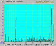
Linearity of the test circuit was actually pretty good. At 2VRMS out, second harmonic varied from -54 to -60dB, third and higher all under -90dB.
Pentodes will give the requisite gain, but linearity is the question- unlike a Mullard input stage, the splitter is unity gain, so the input stage has to swing the full 35V or so needed to drive the outputs. That can get ugly.
Attachments
There are some basics to designing the cascode properly....
Consider the TOP triode as a voltage regulator, ie it is a cathode follower voltage regulator....with a reference voltage on the grid...Your best best is to REGULATE the voltage going to the grid of the TOP tube...this will improve the PSRR and inprove linearity...
This TOP triode is acting as a trans-impedance amplifer.... So you dial in the voltage on this grid you want to get on the lower triode plate... The lower triode is has it's plate voltage fixed by this top regulator tube...You choose an operating point that yields a descent gm...
The key is to not waste too much voltage drop on the lower and top tube.... The lower tube is simply a gm amplifer, use as small a voltage across this lower tube as possible to get the gm where you want it.. SAme with the follower, don't waste more voltage drop than need be... SAve most of the voltage drop for the Load resisitor...Since this will give you the best optimum swing...
Chris
SY said:I was trying to stay with a triode restriction and to use bf's boards (if he can't return them).
Linearity of the test circuit was actually pretty good. At 2VRMS out, second harmonic varied from -54 to -60dB, third and higher all under -90dB.
Pentodes will give the requisite gain, but linearity is the question- unlike a Mullard input stage, the splitter is unity gain, so the input stage has to swing the full 35V or so needed to drive the outputs. That can get ugly.
So, let's test my Pyramid-V
I'm still satisfied by it's sound. First and last stages are pentodes, with triodes in between.
Bring it up here! I'm off on a job interview trip in a few days, but will be back next Tuesday. Anytime after that.
Clearly I have no bias (no pun intended) against pentodes- my little amp uses a pentode output stage. I just think that it will be difficult to get what ends up being a Dynaco input stage to be very linear.
Clearly I have no bias (no pun intended) against pentodes- my little amp uses a pentode output stage. I just think that it will be difficult to get what ends up being a Dynaco input stage to be very linear.
- Status
- This old topic is closed. If you want to reopen this topic, contact a moderator using the "Report Post" button.
- Home
- Amplifiers
- Tubes / Valves
- Pros and cons of Cascoded front ends