Hi,
I just found this thread. First let my say you guy's are doing a awesome job, and you got some great skill's to. I am all so trying to make my own unit, it will be a small 6" unit... hope it will end up to be a full range. But I have a long way to go....
Anyway, you should try looking at depron as a membrane material, I made a vacuum for mine and it wight only 0.9gr for a 6" membrane.. not to bad. And the material has a high damping as well.
Attachments
You could always do a bolt/sleeve/slab construction like the Dynavox woofers are assembled. That wouldn't take much thought at all.
Later,
Wolf
Well i have found some aluminum bars to do the arms, now i need to find 15mm thick aluminum plates. Soon...

Hi,
I just found this thread. First let my say you guy's are doing a awesome job, and you got some great skill's to. I am all so trying to make my own unit, it will be a small 6" unit... hope it will end up to be a full range. But I have a long way to go....
Anyway, you should try looking at depron as a membrane material, I made a vacuum for mine and it wight only 0.9gr for a 6" membrane.. not to bad. And the material has a high damping as well.
Thank you Frank,
I am interested in learning more about depron and your project if you want to share.
Hi Hentai
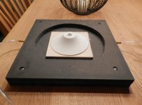
Sorry for the late replay.....I made a vacuum form of plaster and made a little jig for suction, for suction I used a vacuum cleaner. The Depron (3mm) was taped over the jig and the Depron was heated up with a hot air blower, when the Depron is getting bendy (Just a bit soft) the vacuum is set on in a slow manner.
You have to bee very careful when using the hot air blower, Depron is a very good insulator so on side can be hot and the other side cold.. So I think it will be easer to work with if it is heated up with radiated heat, or even better if the hole thing is heated up and vacuum-ed in a oven in one process.
My project:
My project is in a early stage, it should end up with a 6.5” full range unit. It will be using faraday ring's and it will be a double voice coil. The reason for the double voice coil is, for two reasons. First it can be used to ad some extra energy to the coil at higher frequency if needed or it can be used as an extra faraday ring, to lower the induction in the coil.
I will be using magnets not a field coil, I am trying to figure how to make sure that the pol are magnetic saturated with a good margin so it dose not get unsaturated regardless of how much flux is generated in the coil.
Attachments
Hello Frank,
Thank you for reply, it is very interesting to read about it, a very nice jig. I'm not sure how the mold is, but would it be possible to make it from metal (either aluminum or steel) and heat its surface?
How are the acoustic properties of depron compared to paper?
The second voicecoil if shorted im not sure if it will lower inductance but my guess is it will have an impact on Qms as it will seem the former as having a higher conductance. Ofc it will also impact Qes. I hope you can experiment soon and share the results. I am also fighting inductance.
Hi Hentai
As I see it the faraday ring act's like a secondary coil on a transformer. So when using a faraday ring you have a transformer and not just a single coil, this means that the impedens from the sec. winding will load the primer side by N/N. I found this nice dok. http://www.diy-audio.narod.ru/litr/FaradayRingsVoiceCoilImpedance.pdf
Please correct me if I am wrong.
You can make the form from any material realy as long it will hold to about 140 degree C. Paper vs. Depron.. It is to early to tell, but depron has a very high degree of damping and it is ultra light... but time will tell.
Hi Frank, i am familiar with Ahmet Feyz Pirimoglu's paper. We had a few conversations on facebook, i wish he could join this discussion as well.
The reason why i don't believe it will have a big effect on inductance is because it will have a high resistance. Unless you can short all the turns in the second voice coil the resistance even if in shortcircuit will be that of voice coils Re. In my initial tests i made the model Ahmet suggested in spice also thinking the field coil if fed by extremly low impedance power supply will have an influence on inductance. It didnt because it had high Re (Rdc). I found that for a shorting ring to be effective, for that coupling to be of high value the resistance of the shorting turn must be very very small. 0.1 ohms and less. The lower it went below 0.1 ohms the higher the effect it had on inductance.
Granted tho it will lower Qes and i guess that you should verify if that will compensate for the higher voice coil mass. Since your cone is much lighter than your voice coil i believe that it would be advantageous to try to lower voice coil mass as much as possible. In a graph i posted here i tried to see how much of a difference was in overall efficiency between higher vc mass and lower Re. I found that for cone mass close or lower in value than vc mass, this mass has a bigger influence on efficiency and for cone mass higher than vc mass, Re has a bigger influence on efficiency.
I also made dual coils 32 ohms each to work in parallel. I will try in the following days to use one in short and see what happens.
Keep us posted with your project and findings, to check out saturation levels for your magnetic structure you can use FEMM.
Yes i measured it and indeed distortion drops with increased field coil current. I haven't posted the graphs yet because i plan to do these measurements in a more quiet and controlled environment.
While i could get away with outside measurements for frequency response for distortion i need a better place to lower noise floor for useful results.
While i could get away with outside measurements for frequency response for distortion i need a better place to lower noise floor for useful results.
Can some one tell me if the Faraday ring should have electric contact to the pol or not, I can't figure out what is best.
Also.. Do you know what kind of glue to use for holding the wire on the voice coil base.
Hentai, Looking forward to hear what happens when you short one of your wingding on your voice coil.
Is the FEMM a free softweare, and if so where can I find it.
Also.. Do you know what kind of glue to use for holding the wire on the voice coil base.
Hentai, Looking forward to hear what happens when you short one of your wingding on your voice coil.
Is the FEMM a free softweare, and if so where can I find it.
Last edited:
Can some one tell me if the Faraday ring should have electric contact to the pol or not, I can't figure out what is best.
Also.. Do you know what kind of glue to use for holding the wire on the voice coil base.
Hentai, Looking forward to hear what happens when you short one of your wingding on your voice coil.
Is the FEMM a free softweare, and if so where can I find it.
IMHO, definitely should have conductivity between the shorting ring and the pole.
Hi all,
A good choice for glue is hernon. I used it and also used resin. You can apply by brush. If voice coil will not withstand loads of power you can use lacquer as well.
I too believe it is best for copper to have contact with the bolt for the best coupling and highest effect on inductance. It is best tho to use a Fem software to determine position, and physical dimensions of the structure.
I just realised that is might be a life long project for my
I have some questions regarding induction in the coil and the placement of the Faraday ring(s). In the paper by Ahmet Feyz Pirimoglu it is stated that you can use more than one ring so I am looking in to doing just that.
I am trying to make a coil former with a build in Faraday ring. The former is made from tree layers, first layer is a 10 micron alum. Foil with 2 winding... 2th layer is a one layer paper and the 3th. Layger is 2 wingding of 25g/M2 fibreglass, this is all hold together with epoxy resin. This will give a width of 0.2-0.25mm.
Now for the questions:
Hentai, I don't understand the placement of your faraday ring, I would think it has more effect if it was closer to the coil... But I could be wrong. Normally it is placed at the center pole going in to motor itself.
Did you try to do some simulations with more than one ring.
I think a overhung voice coil better in respect to inducting than a underhung, any thoughts on that.
PS. I will post some pic's of the voice coil former if it works out.. and when it is dry.
Hi Frank,
I have tested with shorting ring inside the gap but because the copper material had to be thin in order to fit the gap it wasnt as effective as a thick ring placed just below the gap. The electrical resistance of the ring is much more important to me than placement. If you attach it to the central pole piece the coupling is pretty good.
Sorry for image quality, im not good at taking pics:

Overhung yes has lower inductance but first i wanted the lower distortion of underhung, second if you make the cone light enough (you have) than inductance isnt such a burden.
Personally i think you should drop the idea of using shorting ring in voice coil. It wont be effective being thin and aluminum. It will add to mass and will interfere with damping. Using a copper or silver ring attached to the central pole piece as thick as possible is best imho. Also designing the voicecoil itself in a good way to reduce inductance. as small a diameter as possible, as high a height as possible things like this.
I have tested with shorting ring inside the gap but because the copper material had to be thin in order to fit the gap it wasnt as effective as a thick ring placed just below the gap. The electrical resistance of the ring is much more important to me than placement. If you attach it to the central pole piece the coupling is pretty good.
Sorry for image quality, im not good at taking pics:
Overhung yes has lower inductance but first i wanted the lower distortion of underhung, second if you make the cone light enough (you have) than inductance isnt such a burden.
Personally i think you should drop the idea of using shorting ring in voice coil. It wont be effective being thin and aluminum. It will add to mass and will interfere with damping. Using a copper or silver
ring attached to the central pole piece as thick as possible is best imho. Also designing the voicecoil itself in a good way to reduce inductance. as small a diameter as possible, as high a height as possible things like this.Hi
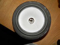
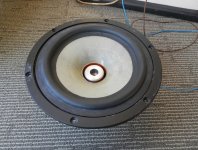
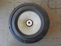
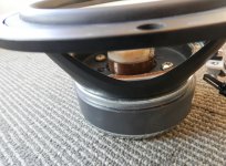
Just some note on what I learned. Depron is to soft a material to convert energy from the voice coil to the membrane at higher frequencies , it will require some other material that are very stiff.
I did a new membrane with 4 layers of 25g/M2 fibre glass, it weight 1.9 g for the membrane alone.
I used a voice coil from a Monarco SPH 170C. The voice coil was glued to the membrane using 5 min. epoxy glue.
This relay works, it sound like a full range now, I compared it to my F200A and the new one sounds like it has more dynamic in the top. This might be the one that I keep, but I got a few ideas I need to try.
Any progress with your project?
Here is some pic's:
Attachments

Last edited:
- Home
- Loudspeakers
- Multi-Way
- Project Ryu - DIY Field Coil Loudspeaker