An update on the works,
I'm still considering the carbon fiber cones, i guess until i tested things wont be clear for me. I love the sound of paper on cones tho so i'm a little stubborn but i will test the carbon in the future as well.
I have modified the magnetic structure meanwhile (i will post about it soon) The new structure will allow for a more precise assembly and mounting of the copper shorting rings.
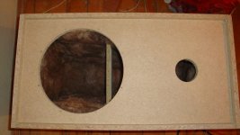
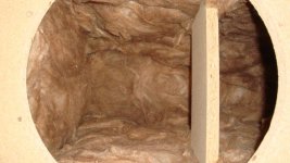
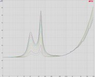
This weekend i made a test reflex enclosure from fiberboard. 110L tuned around 40Hz. I wanted to see the impedance curves with different current through the field coil.
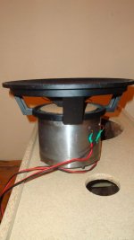
I used a 32 ohm ECCAW voicecoil from tests i did before ( i will post on these as well as soon as i arrange the data) so the lowest Qts value (3Amps through VC) is aprox 0.4.
Here are some pics:


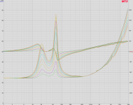
As you can see pretty much a typical behaviour at low frequencies. At high frequencies we see that the impedance drops with increasing current through voice coils. Permeability of plates changes with the changing flux density. We can see some little glitches appearing gradually in the linearity of the curves with increasing current.
I could not associate these glitches with any dips or peaks in freq response, could be resonances too subtle, and with weak current through field coil there is not enough energy to excite them.
Using it in reflex is a waste though of efficiency. The high-mid region would need notch filtering. Horns are the way and that will be done pretty soon.
Some videos playing with it: Ryu DIY Field Coild Loudspeaker - YouTube
I'm still considering the carbon fiber cones, i guess until i tested things wont be clear for me. I love the sound of paper on cones tho so i'm a little stubborn but i will test the carbon in the future as well.
I have modified the magnetic structure meanwhile (i will post about it soon) The new structure will allow for a more precise assembly and mounting of the copper shorting rings.
This weekend i made a test reflex enclosure from fiberboard. 110L tuned around 40Hz. I wanted to see the impedance curves with different current through the field coil.
I used a 32 ohm ECCAW voicecoil from tests i did before ( i will post on these as well as soon as i arrange the data) so the lowest Qts value (3Amps through VC) is aprox 0.4.
Here are some pics:
An externally hosted image should be here but it was not working when we last tested it.
As you can see pretty much a typical behaviour at low frequencies. At high frequencies we see that the impedance drops with increasing current through voice coils. Permeability of plates changes with the changing flux density. We can see some little glitches appearing gradually in the linearity of the curves with increasing current.
I could not associate these glitches with any dips or peaks in freq response, could be resonances too subtle, and with weak current through field coil there is not enough energy to excite them.
Using it in reflex is a waste though of efficiency. The high-mid region would need notch filtering. Horns are the way and that will be done pretty soon.
Some videos playing with it: Ryu DIY Field Coild Loudspeaker - YouTube
Attachments
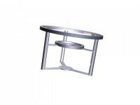
Here is my idea of the frame, will take shape soon.


Attachments


Last edited:
*Pnotus got his reply on pm
I have been listening for a little while now and i am pretty much please with where i am now. There is, of course, room for improvement and this is what occupied my time lately.
The magnetic structure suffered a few tiny but important changes as well as the voice coil. I have underestimated the battle against inductance in an underhung design. The relationship between electrical parameters makes it difficult to make a choice and i still have a couple more options to test and evaluate.
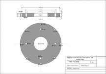
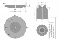
So attached you will find plans for the first version, if there are builders going this path i can provide more info, sketches etc.
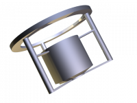
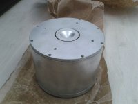
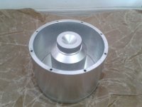
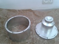
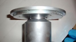
Also some pics with the new motor structure, allows for a more precise assembly, central pole and bottom plate are from a single chunk of metal, a nice change on the gap geometry.


With the new structure i hope i will finally defeat inductance.
As sound goes, high dynamics, impact and so sweet midrange.
I have been listening for a little while now and i am pretty much please with where i am now. There is, of course, room for improvement and this is what occupied my time lately.
The magnetic structure suffered a few tiny but important changes as well as the voice coil. I have underestimated the battle against inductance in an underhung design. The relationship between electrical parameters makes it difficult to make a choice and i still have a couple more options to test and evaluate.
So attached you will find plans for the first version, if there are builders going this path i can provide more info, sketches etc.
Also some pics with the new motor structure, allows for a more precise assembly, central pole and bottom plate are from a single chunk of metal, a nice change on the gap geometry.
With the new structure i hope i will finally defeat inductance.
As sound goes, high dynamics, impact and so sweet midrange.
Attachments
-
 Mag Assembly 1201 pg3.jpg648 KB · Views: 274
 -
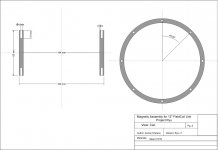 Mag Assembly 1201 pg2.jpg646.6 KB · Views: 357
 -
 Mag Assembly 1201 pg1.jpg663.7 KB · Views: 423
 -
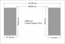 Fieldcoil sketch.jpg701.1 KB · Views: 359
 -
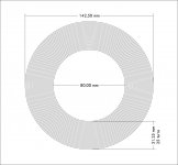 Fieldcoil sketch 2.jpg799.1 KB · Views: 341
 -
 ryuv203.jpg119.7 KB · Views: 208
 -
 ryuv202.jpg125.3 KB · Views: 206
 -
 ryuv201.jpg129.2 KB · Views: 188
Yes, the sketches are for the first version tested. The new version has some improvements that i will need to put to the test.
There is still some polishing to be done and i will upload more detailed pics and rest assured the sketches as well") .
.
Also in page one the view is the central pole piece and the bottom plate. Top plate is on page 3.
I believe the sketches of the first version represent a good foundation for anyone who wants to explore sound with a field coil speaker.
There are a few people that manifested an interest in this design and i hope by the end of the year there will be reviews in some of the audio zines. Much work to do...
There is still some polishing to be done and i will upload more detailed pics and rest assured the sketches as well
.Also in page one the view is the central pole piece and the bottom plate. Top plate is on page 3.
I believe the sketches of the first version represent a good foundation for anyone who wants to explore sound with a field coil speaker.
There are a few people that manifested an interest in this design and i hope by the end of the year there will be reviews in some of the audio zines. Much work to do...
Incredible fabrication skills!
A couple questions:
Besides the "because I can" answer, why use an electromagnet VS. fixed magnet in loudspeaker design? Roughly what size ceramic magnet does this replace at your intended current through the field?
Has anyone experimented using a huge electromagnet motor with fixed magnets (say an array of small neo slugs) attatched to the cone (in place of a coil)? For low frequency applications you have the benefit of high mms and potentially unlimited thermal power handling with a big enough coil?
Thank you hispls,
The main advantages of a field coil design are:
- control over the units' parameters. with a pm driver you can not change any of it's parameters so there is little flexibility in designing a box. with a field coil you can make it suitable for any kind of loudspeaker.
- lasts forever, no demagnetization
- from a DIY point of view, it is a lot easier to assemble than with permanent magnets unless you can magnetize them after assembly (expensive machinery and dangerous to build)
To reach 1.5T in that gap would require a ceramic 5 magnet ring of 220-240mm outer diameter and 70 mm inner diameter. (20mm thick)
Im not sure about unlimited thermal power, even if you make your electromagnet to withstand tons of power, neo magnets don't like high temperatures.
Im not sure about unlimited thermal power, even if you make your electromagnet to withstand tons of power, neo magnets don't like high temperatures.
Too true. I was somehow thinking you could have a huge field coil that wouldn't get hot to the point of demagnetizing your neo. When you do your temperature testing of your field coil, compare that to the danger zone for neodymium.
I know I use some neo based permanent magnets and you can burn up some pretty robust coils long before the neo gets terribly warm to the touch, but little pencil eraser size bits of neo in a huge coil may not fare so well as large neo slugs sandwiched between big lumps of steel.
Hentai.
Thanks for the posts, it is a pleasure to see some radical and creative work.
My compliments on your impressive project. Seems like you have had a lot of fun also.
Looks like you have had fun in FEMM too! Doesn't look like a voice coil will really fit in your simulation Have you tried this with a more realistic return structure?
Best wishes
David
Thanks for the posts, it is a pleasure to see some radical and creative work.
My compliments on your impressive project. Seems like you have had a lot of fun also.
It is possible to construct an underhung radial NdFeB speaker motor with over 2T gap flux by using a magnet-to-magnet topology across the gap.
Looks like you have had fun in FEMM too! Doesn't look like a voice coil will really fit in your simulation
Have you tried this with a more realistic return structure?Best wishes
David
Thank you David, indeed i love working on this project.
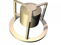
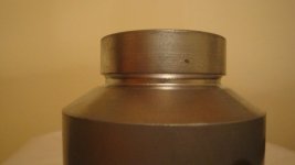
Here is a close shot of the new central pole piece with the T-shaped top.
In that groove i will fit the copper shorting ring. Also with the top plate so you can get an idea of position and such.
I will borrow one of those DSLR cameras from a photographer friend of mine to make better pics these days.
Attachments


Cheers guys,
@Allar88 frame is still not diy. I have a hard time finding a big chunk of aluminum or sheets thick enough to machine the frame parts and what little i found was very very expensive. But 2013 will bring the diy frame i'm sure.
You could always do a bolt/sleeve/slab construction like the Dynavox woofers are assembled. That wouldn't take much thought at all.
Later,
Wolf
- Home
- Loudspeakers
- Multi-Way
- Project Ryu - DIY Field Coil Loudspeaker