hey guys,
i've just finished a paralleled LM3886 (PA-100 style) based power amp and i'm having a weird problem.
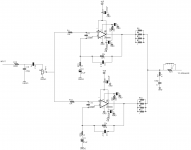
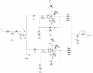
The two LM3886 amplifiers are on separate boards and have their inputs connected by a wire between the two boards.
One board has the zobel network and damped series inductor, the output of the other board again is connected to this one by a wire.
The resistors are all 1% metal film type, hand matched to about 0.5% in the signal paths.
The two sets of four 1Ohm paralleled resistors at the outputs of each LM3886 were used because I couldn't get the 0.1Ohm, 1%, 3W resistors suggested in the application note.
At this stage, both boards work perfectly when not connected to each other, but whenever i connect them, they oscillate rail to rail at high frequency and as a result heat up very quickly.
I have connected the positive and ground terminals of my scope probe to each output (positive end of probe to output of one board, ground lead of probe to output of other board) with the boards unconnected, in an attempt to get an idea of how different the ouput signals were, and there was no visible difference *except* when the volume pot (25k, log) was between about 2 and 4 0'clock, when there was a high frequency signal of about 150-200mV difference between the two outputs. When the volume was turned up more that this, this signal disappeared and the difference once again became negligibly close to 0mV.
I tried to test this because I was under the impression that the biggest problem with the parallel setup is that differences in the outputs cause the two amps to drive each other, although I don't know if that would actually cause the oscillation I'm seeing at the output when the boards are connected.
The power supply is an unregulated 24-0-24 t/f with 9,400uF at each rail, which is putting out about +/-38V.
I have tried with 4Ohm and 8Ohm loads as well as unloaded and the same problem occurrs.
I'm pretty confused. I'm open to the possibility that the fact that the two amps are on two different boards is causing problems due to interference etc.
Does this sound like a grounding issue? I was under the impression that ground loops caused hum, not huge oscillation.
Anyway, if anyone has any ideas or suggestions I'd love to hear them.
i've just finished a paralleled LM3886 (PA-100 style) based power amp and i'm having a weird problem.
The two LM3886 amplifiers are on separate boards and have their inputs connected by a wire between the two boards.
One board has the zobel network and damped series inductor, the output of the other board again is connected to this one by a wire.
The resistors are all 1% metal film type, hand matched to about 0.5% in the signal paths.
The two sets of four 1Ohm paralleled resistors at the outputs of each LM3886 were used because I couldn't get the 0.1Ohm, 1%, 3W resistors suggested in the application note.
At this stage, both boards work perfectly when not connected to each other, but whenever i connect them, they oscillate rail to rail at high frequency and as a result heat up very quickly.
I have connected the positive and ground terminals of my scope probe to each output (positive end of probe to output of one board, ground lead of probe to output of other board) with the boards unconnected, in an attempt to get an idea of how different the ouput signals were, and there was no visible difference *except* when the volume pot (25k, log) was between about 2 and 4 0'clock, when there was a high frequency signal of about 150-200mV difference between the two outputs. When the volume was turned up more that this, this signal disappeared and the difference once again became negligibly close to 0mV.
I tried to test this because I was under the impression that the biggest problem with the parallel setup is that differences in the outputs cause the two amps to drive each other, although I don't know if that would actually cause the oscillation I'm seeing at the output when the boards are connected.
The power supply is an unregulated 24-0-24 t/f with 9,400uF at each rail, which is putting out about +/-38V.
I have tried with 4Ohm and 8Ohm loads as well as unloaded and the same problem occurrs.
I'm pretty confused. I'm open to the possibility that the fact that the two amps are on two different boards is causing problems due to interference etc.
Does this sound like a grounding issue? I was under the impression that ground loops caused hum, not huge oscillation.
Anyway, if anyone has any ideas or suggestions I'd love to hear them.
Attachments
1) A picture of your test setup would be helpful>
2) use 2 probes instead of one w/ground/earth at an output of an amp. Even when your PS is floating there is a HF ground loop! Or Measure gain difference with an RMS tone and a DVM. After the gains are matched as close as you can also look at square waves for signs of instability.
3) Your problem is most probably you need a seperate RC zobel at the output of each amp closer 0.1 UF and 4.7 ohm.
hi infinia,
sorry, the zobel is actually 0.1uF and 4.7Ohm, that was an error in the schematic.
i'll get pics up if i can.
what did you mean by there being a HF ground loop when my power supply is floating?
i tried testing the difference between the outputs that way because i only have a single trace scope with the one probe.
I have measured the gain difference with an RMS tone and a crappy DMM, as far as i could tell the gains were very well matched.
I'll give the extra rc zobel a shot and see if it helps at all, but i thought zobels were intended to counterract the changing impedance of a speaker load; this problem occurrs even when the amp is unloaded.
Thanks for the reply,
mitch
first thing I would do is lower R1 and R13 to about 1k.
if that doesn't help then:
Are you using a 47k pot?
try and change your input to look something like this schematic:
PA100 DIY 2x LM3886 in parallel gainclone audio amplifier
i am guessing you used that as a design guide anyway?
You can put the pot before the input.
I don't see the use for two zobel networks on the output? and c7 should be 100nF and not 100pF.
Hi Mitch
the RC zobels are to keep the amp happy near the unity gain freq ie stable phase margin. They like to be located near the IC as well as PS decoupling 220uF + 0.1uF.
cheap DMM sb be ok using low freq tones 400Hz and near full scale. 1.990 V
Let's calculate the gain mismatch if you want. Don't forget to look at square waves.
first thing I would do is lower R1 and R13 to about 1k.
I don't see the use for two zobel networks on the output? and c7 should be 100nF and not 100pF.
Hi TangM
Agreed about input circuitry. I think the impedance looking out from non-inv input should be close to Rf at DC for offset and noise.
Normally 1 zobel should be good, but this is on 2 separate boards with unknown to me (wired ground return paths and output inductance).
Dear,
1: Measure the DC offset from each individual amplifier.
2: Route all grounds to a separate star ground, (give separate ground tracks to the Zobel, decouple caps, and line signal ground).
3: like others suggested, make the input impedances equal.
In my opinion it is never wise to build chip-amps in parallel without a DC servo. A few DC mV. difference can cause huge current loops between the two chips.
With kind regards,
Bas
i had similar problems with my pa100 (using the Shine7 boards - 3 chips).
The power on each board was stable untill the boards ran together from the same PSU.
I would start by - Disconnecting the output resistors for each chip and and see if the PSU holds stable. Check the gain for each chip. Then bring back the output resistors one by one checking each time the PSU is stable. Try to isolate which chip circuit it causing the problem.
Last edited:
Yes.From your diagram there looks to be a dc path between the two chips.
I would rearrange the circuit to get rid of that.
AC couple the input to both chips.
I have repeatedly advised that paralleled inputs cannot be used. It upsets the input offsets, both currents and voltages.
One must AC couple all paralleled inputs.
Yes.
I have repeatedly advised that paralleled inputs cannot be used. It upsets the input offsets, both currents and voltages.
One must AC couple all paralleled inputs.
Dear Andrew,
You are right here. However it should work if you remove the 220p capacitors, and make the impedances for the +IN and - arm equal in respect to the feedback arm and ground. At least my designs always worked flawless this way with no oscillation and DC offset bellow 60 pV. Note this is with a DC servo per chip and a DC servo on the opamp that drive the chips.
A DC servo is a must if you parallel those chips. Else you never have truly control over the DC over time when specifications change due temperature difference and aging.
With kind regards,
Bas
What are the mechanisms of full scale oscillations here folks.
AC gain matching is much more critical for balanced out high currents. These things can be made to work with small offsets so what 100mA DC may flow between the outputs. Besides this help bias more towards class A away from crossover region.
AC gain matching is much more critical for balanced out high currents. These things can be made to work with small offsets so what 100mA DC may flow between the outputs. Besides this help bias more towards class A away from crossover region.
Yikes 3 servos! Also why do you need an op-amp driving the chip amp at DC?Note this is with a DC servo per chip and a DC servo on the op-amp that drive the chips.
How bad is the Vos drift w/o servos for one LM3886? I would expect the drift of each to rise together cancelling the need./ esp since this a home-brew DIY monolithic amp with good low temp range after warm-up. Discrete amps are not as good as these guys in this regard.
There is an art to good servo design, that if done improperly can degrade any good chip amp. ie with any complex solution to IMO a small problem creates a whole new set of other problems. I believe in KISS.
Yikes 3 servos! Also why do you need an op-amp driving the chip amp at DC?
How bad is the Vos drift w/o servos for one LM3886? I would expect the drift of each to rise together cancelling the need./ esp since this a home-brew DIY monolithic amp with good low temp range after warm-up. Discrete amps are not as good as these guys in this regard.
There is an art to good servo design, that if done improperly can degrade any good chip amp. ie with any complex solution to IMO a small problem creates a whole new set of other problems. I believe in KISS.
Dear Infinia,
Don't worry. I spent a lot of time and attention just to the servo's. My real life experience is, that you can get much more performance and long term loud listening levels out of those chips in a BPA design if you keep the DC as low as possible. My servo designs are part of the balanced arms of the chip, in order to keep resistance equal for + and - inputs. If done properly it reduce noise and offset issues even further. The input servo is feed to the compensation system of the input single input opamp. This is to regulate away the first 20mV or so offset from a active crossover. If you leave out the input DC servo, or a cap, then the chip servo's are working full force all the time with voltages that can get close to the limits of those opamps, and will induce noise.
The DC drift over temperature is not so good from the LM3886's, that is why I never understood why Jeff Rowland does it with the potentiometers. If u heat up the system, the DC specs change. Therefor I believe that a DC servo is a must. On the other side, Jeff Rowland have one piece aluminum cases, so plenty of cooling.
My BPA300 system is inspired from but different then the application sheet from National, and outperform's that design in measurement, and listening session. I have one copied from the national application note as well for comparison. If I have more time lateron this month I will post this concept, and who knows if there is enough interest I can offer some PCB's as well.
With kind regards,
Bas
Last edited:
Hi Bas
Maybe you offer us a solution? I still think DC offsets are not a problem for these paralleled LM3886s. The biggest contribution is initial offset and that can be trimmed or tweaked out, more or less with simpler means. After that with devices mounted on the same heatsink should track quite well.
Maybe some initial DC bias at the output is better for higher biased class AB listening.
PS I still believe in simple things in life
Look forward to anything you can post showing your designs.
Hi Bas
Maybe you offer us a solution? I still think DC offsets are not a problem for these paralleled LM3886s. The biggest contribution is initial offset and that can be trimmed or tweaked out, more or less with simpler means. After that with devices mounted on the same heatsink should track quite well.
Maybe some initial DC bias at the output is better for higher biased class AB listening.
PS I still believe in simple things in life
Look forward to anything you can post showing your designs.
Dear Infinia,
I am on the same page with you, Me too love and prefer simplicity in designs, and often it pays off in transparency and imaging. But in that matter, a single good implemented chip outperforms the bridge/parallel design.
If you go for bridge/parallel, in my opinion you can't keep it simple anymore without sacrificing reliability and performance. It might look good, if those chips keep fighting each others DC offset for some class A biasing, but in reality with 6 of those chips on a heat sink, things heat up very fast. Must faster and hotter then you want. Spike protection kicks in before you know, and sounds awful. (one of the limitations of this chip). Myself I underestimated this heating big time as well. But again 6 of those chips with only a slightly offset difference get really really hot. Measurements showed as well that this "heating" (or higher class A biasing, just how u want to call it
 ) don't contribute any good, Distortion rise with every 5 degrees Celsius.
 It is not for nothing the application note came up with DC servo's in first instance.
I stick to the opinion that for best performance LM3886 BPA200/300 or a PA100/200 that those extra complications are necessary for good performance and long term high current use. The national application note gave an excellent design example which everyone can simply copy/paste if you want to go for safe. However things can be improved
I promise, I will post soon. I just need to re-draw it for DIY application, since my design is part of a bigger concept.Ps. I also have the opinion that a DC servo can be a really good thing, if designed smart. This extra opamp that feeds signal back can be beneficial, and serve the same time as virtual ground for example. It is all about implementation.
With kind regards,
Bas
Last edited:
- Status
- This old topic is closed. If you want to reopen this topic, contact a moderator using the "Report Post" button.
- Home
- Amplifiers
- Chip Amps
- Problem with parallel LM3886 (PA 100)