Hi Basand the chipamps will have an offset around 1mV. With balancing the inverting servo (as I did) u can reach a DC offset as low as 6uV per chip, and this keeps the system really stable and cool with no need for 0.1% gain matching resistors. However if u go all the way differential as in my last example, those 0.1% resistors strongly improve the CMMR of each chip.
Using servos takes care of DC offset only. The LM3886 DC offset can be much greater than 1mV for ~20K inputs BTW (see test Fig on the Data sheet ), with 20-30 dB gain.
But more importantly > You still need precision AC gain matching to keep the LM outputs dynamic cross currents in check. right.
Dear Infinia and abraxalito,
Of course AC matching with 0.1% resistors is better, but my experience is that the constant DC flowing between the chips heats them up much more then differences in the AC music signal. Let say like this, in practice I got heating up problems with DC offset more then 3mV between each chips. In the same setup with the same 1% resistors this heating was solved after the DC servo solution. Like you can see I am more of a practical guy, who just build things and try out. 0.1% metal-film 1206 resistors are fairly expensive.
The next answer is subjective and not based on facts. In my human opinion the system sound much better with DC servo's. More black and 3D. Only explanation I can give is that the chips are far less stressed up in this configuration and are much cooler in operation then without. I think this thermal stress degrade sound quality.
Secondly, in my setup I think the benefit is that the positive leg has reference to the virtual ground of the servo opamp instead of ground. This gives a better impedance matching and floats the circuit above (dirty) ground. I can only guess at this point, since I didn't measure directly between A/B but I think this is also a cause of the better sound quality in comparison to the standard BPA300
In terms of speed (not measurable slew-rate, but the perception of speed in sound reproduction with for example percussion) I still think a single simple nested chip setup is still the best. See attachment. The bass of this single chip nested setup is so tight that it is scary and u have the illusion you listen to a big nuclear power plant in control.
However if you want more power and authority the serial/parallel set-up offers more grunt, with in my opinion at a little cost of the "alive" feeling.
Theoretical the bridged setup should offer twice the slew-rate, but the single nested chip solution gives me a more "fast" sound experience.
Well who knows it is time for a next experiment. A nested bridged/parallel setup
Note about the attachment. This is the smallest, cheapest but best sounding amplifier I've ever built. (Believe it or not, but better then my Bryston 7BSST mono's and better then my other discrete designs). I first built it with the OPA549. In this case the OPA549 itself only get a voltage gain of 3. the rest is up to the NE5534. The OPA549 have a relative small open-loop bandwidth, and therefore gain must be kept to a minimum.
-Opamp is NE5534 for two reasons,
1: Because of the comp pins I can slow the opamp down to match to lower speed of the LM3886. I prefer to do this in the VAS which the NE5534 allows so less compensation is needed in the global feedbackloop.
2: The NE5534 allows me to bypass it's output stage and basically use it as VAS only. (take the output from pin 5) The output of the VAS drives relative small currents to the 3886 chips, and therefore will be operate in class A. You can expand this class A range by adding a current source to pin 5 or simple a resistor from V+ to pin 5. I didn't try that yet, but like with everything, not to much, enough is enough.
The system is DC coupled and the servo feeds pin 8 of the NE5534 to adjust the bias inside the chip. Note, this is only meant for slight offset adjustment, and no more then 30mV. max input offset is allowed. Else the distortion and noise will rise. The servo is connected with 100k to pin 8 of the NE5534, however in real life, pin 1 must also be connected with 100K to ground. The simulated model doesn't have this pin, so it is not visible on the schematic.
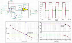
The circuit was not easy to stabilize, but after some tweaking and calculating the result is pretty neat. Phase is under control sand square-wave look decent. Once the right compensation is there, the system is stable.
I build the same circuit with a LM3886, but of course with more gain for the LM3886 part. For less experienced readers out there, do not attempt to build this circuit yet for two reasons.
1: the VAS output from the NE5534 only has limited current capability and is not protected. I destroy a few when the LM3886 got in thermal shut down, and the VAS stage of the NE5534 destruct itself by amply itself infinity cause of lack of feedback (happends when the LM3886 is in the loop and shut down). I am working on a protection circuit, that if the LM3886 shut's down, that the NE5534 get muted.
2: In this configuration there must be a DC protection in cause of a fault. I am working on it and will come back on it later.
Other then that, it sounds fabulous. It is amazing that a system consist of only a few $$ of parts can sound this good, and blow away many expensive commercial products. In comparison to the former circuits the improvement in S/N is 19 dB! Needless to say, the system is black silent with a total appearance of noise, even with your ear to the tweeter. (thanks to the so hated NE5534)
With kind regards,
Bas
Of course AC matching with 0.1% resistors is better, but my experience is that the constant DC flowing between the chips heats them up much more then differences in the AC music signal. Let say like this, in practice I got heating up problems with DC offset more then 3mV between each chips. In the same setup with the same 1% resistors this heating was solved after the DC servo solution. Like you can see I am more of a practical guy, who just build things and try out. 0.1% metal-film 1206 resistors are fairly expensive.
The next answer is subjective and not based on facts. In my human opinion the system sound much better with DC servo's. More black and 3D. Only explanation I can give is that the chips are far less stressed up in this configuration and are much cooler in operation then without. I think this thermal stress degrade sound quality.
Secondly, in my setup I think the benefit is that the positive leg has reference to the virtual ground of the servo opamp instead of ground. This gives a better impedance matching and floats the circuit above (dirty) ground. I can only guess at this point, since I didn't measure directly between A/B but I think this is also a cause of the better sound quality in comparison to the standard BPA300
In terms of speed (not measurable slew-rate, but the perception of speed in sound reproduction with for example percussion) I still think a single simple nested chip setup is still the best. See attachment. The bass of this single chip nested setup is so tight that it is scary and u have the illusion you listen to a big nuclear power plant in control.
However if you want more power and authority the serial/parallel set-up offers more grunt, with in my opinion at a little cost of the "alive" feeling.
Theoretical the bridged setup should offer twice the slew-rate, but the single nested chip solution gives me a more "fast" sound experience.
Well who knows it is time for a next experiment. A nested bridged/parallel setup
Note about the attachment. This is the smallest, cheapest but best sounding amplifier I've ever built. (Believe it or not, but better then my Bryston 7BSST mono's and better then my other discrete designs). I first built it with the OPA549. In this case the OPA549 itself only get a voltage gain of 3. the rest is up to the NE5534. The OPA549 have a relative small open-loop bandwidth, and therefore gain must be kept to a minimum.
-Opamp is NE5534 for two reasons,
1: Because of the comp pins I can slow the opamp down to match to lower speed of the LM3886. I prefer to do this in the VAS which the NE5534 allows so less compensation is needed in the global feedbackloop.
2: The NE5534 allows me to bypass it's output stage and basically use it as VAS only. (take the output from pin 5) The output of the VAS drives relative small currents to the 3886 chips, and therefore will be operate in class A. You can expand this class A range by adding a current source to pin 5 or simple a resistor from V+ to pin 5. I didn't try that yet, but like with everything, not to much, enough is enough.
The system is DC coupled and the servo feeds pin 8 of the NE5534 to adjust the bias inside the chip. Note, this is only meant for slight offset adjustment, and no more then 30mV. max input offset is allowed. Else the distortion and noise will rise. The servo is connected with 100k to pin 8 of the NE5534, however in real life, pin 1 must also be connected with 100K to ground. The simulated model doesn't have this pin, so it is not visible on the schematic.
The circuit was not easy to stabilize, but after some tweaking and calculating the result is pretty neat. Phase is under control sand square-wave look decent. Once the right compensation is there, the system is stable.
I build the same circuit with a LM3886, but of course with more gain for the LM3886 part. For less experienced readers out there, do not attempt to build this circuit yet for two reasons.
1: the VAS output from the NE5534 only has limited current capability and is not protected. I destroy a few when the LM3886 got in thermal shut down, and the VAS stage of the NE5534 destruct itself by amply itself infinity cause of lack of feedback (happends when the LM3886 is in the loop and shut down). I am working on a protection circuit, that if the LM3886 shut's down, that the NE5534 get muted.
2: In this configuration there must be a DC protection in cause of a fault. I am working on it and will come back on it later.
Other then that, it sounds fabulous. It is amazing that a system consist of only a few $$ of parts can sound this good, and blow away many expensive commercial products. In comparison to the former circuits the improvement in S/N is 19 dB! Needless to say, the system is black silent with a total appearance of noise, even with your ear to the tweeter. (thanks to the so hated NE5534
)With kind regards,
Bas
Attachments
Last edited:
Sebastiaan said:No, the servo opamps going to cost some $$ unfortunately (I agree here with Infinia, it ain't cheap). The Ne5532/34 have bipolar inputs and you need a FET opamp for DC servo's. The same time the offset and drift must be really low as well for the DC servo. Afterall the DC offset of the chipamps will be as low as the servo opamp.
I use LF411 (not LF411A) for my servo design. It has better specs than the NE5532 for offset and drift, but costs about $1.50. Still not bad considering all else.
I use LF411 (not LF411A) for my servo design. It has better specs than the NE5532 for offset and drift, but costs about $1.50. Still not bad considering all else.
a LF411 will do, but is far inferior to the OPA2604 in this application. The OPA2604 in my line level servo can take the DC level down to 6uV. The LF411A as much as 900uV. Also the LF411 induce slightly more noise into the circuit then a OPA2604 do. As bonus the OPA260y is a dual opamp, so in a stereo channel you have two DC servo's
I am still searching for a even better alternative for the OPA2604, but it is hard to find. Any suggestions?
With kind regards,
Bas
Btw. In accordance to this topic I just read the LM4780 data-sheet. Interesting is page 8 for parallel setup, where they use those caps again from feedbackloop to ground. No servo's. I expect problems as well with this chip in this configuration. Even worser, two amps in on die, must heat up even more!
With kind regards,
Bas
I just read the LM4780 data-sheet. Interesting is page 8 for parallel setup, where they use those caps again from feedbackloop to ground. No servo's. I expect problems as well with this chip in this configuration. Even worser, two amps in on die, must heat up even more!With kind regards,
Bas
Btw. In accordance to this topic
With kind regards,
Bas
Yes you mean the RC output zobels. Those values are important for loop stability. If you simulate gain and phase margin for many audio amplifiers you will see what their importance is. There are many factors for insuring phase margin under all conditions of output loading, drive levels, and even input loads ie shorted/open and every impedance/phase in between. I wouldn't second guess the National engineers unless you have advanced or insider knowledge.
Servos are not easy and they are not the end all answer to paralleling these monolithic amps in pairs. But once you start having to add $5 worth of parts to add another $7 chip amp at some point a little light bulb will turn on. National is like usoft once your in bed with them you have to commit entirely.
Last edited:
Yes you mean the RC output zobels. Those values are important for loop stability. If you simulate gain and phase margin for many audio amplifiers you will see what their importance is. There are many factors for insuring phase margin under all conditions of outout loading, drive levels, and even input loads ie shorted/open and every impedance/phase in between. I wouldn't second guess the National engineers unless you have advanced or insider knowledge.
Dear Infinia,
No no. I am not talking about the Zobels. I am talking about Ci1 and Ci2 on page 6, which are connected from the feedbackloop to ground in order to make the amplifier unity gain at DC level. Like abraxalito pointed out in the other thread, those tolerance difference from those electrolytics can be problematic for the AC response, (the chips are not equal) and can make the chips to oscillate, once combined together. Hence the many problem reports we read here with paralleling the chips.
I wasn't talking about the Zobel's. However now you mention them, I don't believe National has a deep rocket science behind the Zobel values, since they use the same values for bridged as parallel operation. In real life the bridged application, each amplifier sees only half of the loudspeaker serial impedance, so the values should differ for bridged. Besides one never know which load will be connected to a general amplifier.
2.7 Ohm seems to be a very low value and not the average speaker load.
Zobel can be calculated by:
Revc= Resistance electrical voice coil
Rz= R Zobel
Cz = C zobel
Rz = Revc
Cz = Levc / Revc2
With kind regards,
Bas
Last edited:
No No those zobels on the data sheet are for the amps only!! loading down near the unity gain frequency there is some peaking of the follower stages internally at light loads. control systems stuff <loop phase margin ie feedback stability>
it's kinda funny. these are not for speakers at all.
it's kinda funny. these are not for speakers at all.
Last edited:
No No those zobels on the data sheet are for the amps only!! loading down near the unity gain frequency there is some peaking of the follower stages internally at light loads. control systems stuff <loop phase margin ie feedback stability>
it's kinda funny. these are not for speakers at all.
Dear Infinia,
Sorry but I can;t follow you anymore here. In my understanding, the capacitors Ci1 and Ci2 forms a DC block to ground in order to get full DC fedback at the inverting input, in order to get the DC offset to be corrected. The value just must be big enough to pass the full AC band-width to ground, to set the feedback level.
The point is, even with 0.1% tolerance resistors, those electrolytic's have huge tolerance difference, so the amplifiers will never be equal, and can cause problems in parallel operation.
With kind regards,
Bas
Regarding paralleling chip amps notice the supply bypasses are increased 0.1+10uF+1000uF for better low freq coupling between amps. I'm sure there is some relationship between the amount of LF extension of Ci and the DC supply time constant needing to be much higher than the inputs. So you need more DC bypass and avoiding bigger caps on the inputs to keep out of trouble say Ci <5% or less of Cbypass total.
Last edited:
Dear Infinia,
The point is, even with 0.1% tolerance resistors, those electrolytic's have huge tolerance difference, so the amplifiers will never be equal, and can cause problems in parallel operation.
With kind regards,
Bas
so are you saying that if one amp has a corner frequency of say 8 Hz, and another has 20% lower at 6.4 Hz that they somehow don't play together now?
so are you saying that if one amp has a corner frequency of say 8 Hz, and another has 20% lower at 6.4 Hz that they somehow don't play together now?
Dear Infinia,
That is not what I say, that is what I assume reading the post from abraxalito. Seeing how many people have trouble with paralleling chip amps, his observations sound very likely. Me never used those caps and never had problems with any paralleled chip amp.
http://www.diyaudio.com/forums/chip-amps/153501-lm3886-x-2-parallel-3.html#post1958213
With kind regards,
Bas
Last edited:
Well I'm not seeing anything like your assumption then > by abraxalito conclusion says you want to increase Ci value. No mechanisms here explained?
Besides I trust test and measurements over Sim models nobody else uses?
Wel Infinia, If I ever would got problems myself I would measure i for sure, but I will never use those electrolytics from feedback to ground anyway. But it is odd to seem so many with parallel chipamp problems over here, so the truth must be somewhere in the middle, and it isn't coincidence all those run into trouble.
I real life (no sims) my servo designs work very reliable day in day out. Doesn't say it can't work otherwise, of course it can, but then it require some engineer skills and one must know what one is doing. Since many people blind copy the app sheets (which doesn't have to be a bad thing) they are often not capable to solve the problem in case the app sheet was a bit off
With kind regards,
Bas
So Bas, how do servos make paralleled chips work with only 1% resistors? You use fairly large sharing resistors and don't mind an amp or so flowing between chips? How much power output did you get with your 12 chip design? Very curious about that as I'm currently doing a mere 4 chip (8 amps) one. Oh, and there have been others saying that paralleled amps just don't sound as good as single ones - have you heard any degradation between a single and paralleled design with your servos?
Sorry,
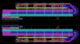
Forgot to answer your other questions. I run the system on 27 volt supply rails, and the power ratings I got was 32.7 volt in all loads up to 2Ohm, without sag, However, below 4 Ohm I could only measure with fast pulses, because my dummyloads are not capable to handle the heat and power.
I can't show the whole project yet, since it is not totally finished, but so far so good. This is how the boards look alike. (more or less, because the final boards had some changes)
With kind regards,
Bas
Attachments
Last edited:
Sebastian, I have ALWAYS wanted to try this. There are several app notes from Analog Devices where they put a precision opamp in the loop with a fast one (back in the days of video opamps) and achieved great results. I am not sure if you will need to "slow down" the 5534 or not. It may force the LM3886 to respond faster, but then again it may cause issues. Once again I am very interested in you final design. The board looks good. I would contribute to the cause of getting them made should you do any kind of group buy.
Thanks,
Jules
Thanks,
Jules
Sebastian, I have ALWAYS wanted to try this. There are several app notes from Analog Devices where they put a precision opamp in the loop with a fast one (back in the days of video opamps) and achieved great results. I am not sure if you will need to "slow down" the 5534 or not. It may force the LM3886 to respond faster, but then again it may cause issues. Once again I am very interested in you final design. The board looks good. I would contribute to the cause of getting them made should you do any kind of group buy.
Thanks,
Jules
Dear Jules,
Trust me, U do need to slow the NE5534 down, else square wave reroduction ring all over your ears
I've bin there done it.The board above isn't for DIY purposes, but I am working on a DIY version, but there will be a new surprise. I did something different with nesting and feedback I didn't discuss yet here, but it will be amazing
, I just need a little more time for the finalizing. With kind regards,
Bas
a LF411 will do, but is far inferior to the OPA2604 in this application. The OPA2604 in my line level servo can take the DC level down to 6uV. The LF411A as much as 900uV. Also the LF411 induce slightly more noise into the circuit then a OPA2604 do. As bonus the OPA260y is a dual opamp, so in a stereo channel you have two DC servo's
I am still searching for a even better alternative for the OPA2604, but it is hard to find. Any suggestions?
With kind regards,
Bas
Sure, the OPA2604 may be a lot better, but it's also 3-4 times the cost, and almost the cost of a LM3886 itself. Also, I would never use a single chip for two separate channels in an amp.
BTW, love your servo design (the single chip one with "virtual" ground), I might have to try it out sometime.
Cool. I look forward to it. I am going to start experimenting with servo's again. I once spent way to long troubleshooting one with a 5532 used for the opamp. Yes... I know it is bipolar and not suitable. I'm a fan of OP2134's OPA-2134
I use them a lot for audio stuff. This is my first time delving into power amps though.
Jules
I use them a lot for audio stuff. This is my first time delving into power amps though.
Jules
Hi guys.
Sorry for the huge delay in reply, been busy with uni etc.
I have tried a few of your suggestions, but the problem is still occurring.
A schematic of the current design is attatched.
infinia, as you suggested, i tested with a square wave and found oscillations occurring identically with both boards, which were quite severe. I reduced the input resistors to 1kOhm from 10kOhm as suggested, which reduced the oscillations somewhat. I then removed the 220pF caps across the inputs of the amps, which basically totally eliminated the oscillations.
I measured the gains with a 80Hz sine both with the 'scope and with a dmm, they were identcal to within the accuraccy of the DMM (10mV) and appeared identical on the 'scope.
I removed the pot and individually AC coupled and terminated the inputs to both boards.
I've also just noticed a hum from the transformer whenever i turn it on with the boards connected, which is probably just due to the massive current draw when the amp is oscillating, but it reminded me of something you said about HF loops in the power supply infinia, what did you mean by that?
I have no idea what the problem is.
The boards are homemade, of my design, so I can't discount the possibility that there are ground loops, but even if there were, would ground loops cause HF rail to rail oscillation only when the amps are connected?
Any more suggestions would be great. I'm not particularly interested in using a DC servo because I know this can be done without one, and I'm fairly sure that dc offset is not the problem..
Anyone have any more suggestions?
- Status
- This old topic is closed. If you want to reopen this topic, contact a moderator using the "Report Post" button.
- Home
- Amplifiers
- Chip Amps
- Problem with parallel LM3886 (PA 100)