The build matches the schematic, i checked 5 times before powering up.
The headaches seem to be unrelated to this amp, I am getting them when listening to my car stereo.
I will update the schematic and post photos of the square wave later today. I wanna hit the gym and see if this audio dealer is open today first.
The headaches seem to be unrelated to this amp, I am getting them when listening to my car stereo.
I will update the schematic and post photos of the square wave later today. I wanna hit the gym and see if this audio dealer is open today first.
")
HF Guy:.. http://i79.photobucket.com/albums/j159/hfguy/DSC01951.jpg?t=1303595391
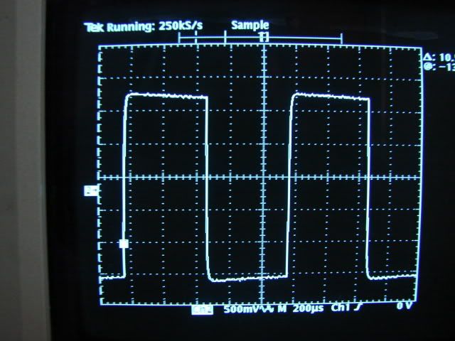
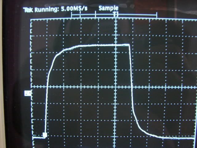
That 10K squarewave with global nfb doesn't look happy and if it is with global nfb then the 1st stage Zobel is incorrect and or the global feedback cap values.Getting this right is one of the hardest tasks of UL push-pull amps as these components interact. I will get my revision notes out.
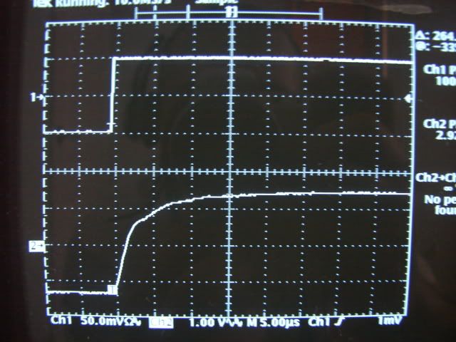
Don't omit the screen zobels...these will effect the knee of the squarewave and avoid a step response in the waveform. The nub problem: all UL o/p trannies with 20-40% screen to each half primary generally has a poor leakage inductance figure compared to whole primary. It is an inherent problem and the leakage capacitance will try and resonate with the leakage inductance, all it takes is a little gain from the o/p tubes, and the purpose of the Zobels, is to quench it..
Remember high gm tubes will oscillate when one doesn't expect them to.
You didn't mention the measuring power levels......close to full poke or around 1W level ?
The bandwidth of the Plitron should master a 10K square wave with ease.
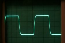
Compare this waveform of my 150W amp using a good quality E&I core....I would have expected a Plitron to equal or better the waveform I've provided and it looks the circuit is applying the brakes, not the output transformer.
If I've missed something, where's the remainder of the input & drive circuit ?
richy
That 10K squarewave with global nfb doesn't look happy and if it is with global nfb then the 1st stage Zobel is incorrect and or the global feedback cap values.Getting this right is one of the hardest tasks of UL push-pull amps as these components interact. I will get my revision notes out.
Don't omit the screen zobels...these will effect the knee of the squarewave and avoid a step response in the waveform. The nub problem: all UL o/p trannies with 20-40% screen to each half primary generally has a poor leakage inductance figure compared to whole primary. It is an inherent problem and the leakage capacitance will try and resonate with the leakage inductance, all it takes is a little gain from the o/p tubes, and the purpose of the Zobels, is to quench it..
Remember high gm tubes will oscillate when one doesn't expect them to.
You didn't mention the measuring power levels......close to full poke or around 1W level ?
The bandwidth of the Plitron should master a 10K square wave with ease.
Compare this waveform of my 150W amp using a good quality E&I core....I would have expected a Plitron to equal or better the waveform I've provided and it looks the circuit is applying the brakes, not the output transformer.
If I've missed something, where's the remainder of the input & drive circuit ?
richy
Attachments
- Status
- This old topic is closed. If you want to reopen this topic, contact a moderator using the "Report Post" button.