Elso:
Sorry, I've read this thread another time but I still didn't get why my ferite beads aren't ok. Is this because they use 2 beads 'capacitive coupling?)
Maybe I'm too tired too...
Peranders:
I learnt it the hard way (cf my recent thread). Either I live in a very RF polluted area, or my scope is very sensitive to HF garbage. But with a classical ground wire on the probe, I got more noise than signal when in 20mV sensitivity.
And when I say it draws 16mA, it's not the comparator but the whole clock. In other words, when I connect an amperemeter between the battery and the clock's "+" connector, it displays "16mA"
And it's clearly not ripple. There are 2 reasons for this:
-I'm using batteries
-ripple looks like this \|\|\|\|\|, not __|__|__|__.
F.K.L.Chan
No, I haven't tried to change the cap. But on the cap tester it measures 0.1uF.
Bypassing the coil (but only with a piece of wire, put by hand on the PCB) won't help much. The peaks are only reduced by 20%
Bernard: you can see pictures of my output squarewave on another thread, if it's what you're referring to
Bricolo,
Most of the standard ferrite beads will work fine on Kwak clock, at least the three in the datasheet you posted do, just BL02 can provide a better result.
I am confuse now why no square wave when using battery, please try replace a new 0.1uF, then meansure again, if the result still the same, parallel a 10uF-47uF Os-Con and see what will happen. I have some oscon here, leave me e-mail if you want, i can mail it to you, my e-mail fkl_chan@hotmail.com
PS: why i can't display my e-mail address, anyone can help?
Re: to search or not to search.....
Really very similar. Doesn't look very good.
You can look at it like a very groundnoisy signal :-(
Andypairo said:Dosen't look that different..
Really very similar. Doesn't look very good.
You can look at it like a very groundnoisy signal :-(
Hi,
Are you guys having problems with noice on the player with Kwak Clock?
I built mine on veroboard and can't get rid of the noice.It is very little but it is there.Coaxial cable helped a bit.
I'm building another one ,this one with ground plane.
If I only find double sided veroboard with ground plane.
Bartek
Yes,it's not dead quiet in the speakers like with internal clock.
It's not power supply kind of noise but rather higher in frequency.
It also depends on the location of the clock PCB,but I kind of can't get rid of it completely.
I think ground plane on the clock PCB would help.
Bartek
It's not power supply kind of noise but rather higher in frequency.
It also depends on the location of the clock PCB,but I kind of can't get rid of it completely.
I think ground plane on the clock PCB would help.
Bartek
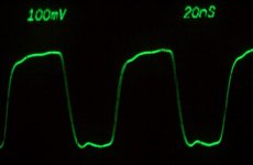
The SAA7220 is also happy with this adjustment.
Amplitude is smaller but still 0.5V reserve to trigger point.
When further decreasing amplitude, severe distortion and disc read failure occurs very suddenly.
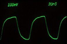
I do not know how important is slew rate, but maybe a more smooth signal like this here gives less noise:
Amplitude is smaller but still 0.5V reserve to trigger point.
When further decreasing amplitude, severe distortion and disc read failure occurs very suddenly.
I do not know how important is slew rate, but maybe a more smooth signal like this here gives less noise:
Attachments
")
Bricolo,
The voltage pulse are not cause by the bead, it should be cause by the impedance of the decoupling cap, there are no voltage pulse before the bead because the bead blocks the high freq. noise, i can say the beads that you are using work very well.
what you need to do is parallel a small low ESR ecap to the 0.1uF.
Leo
The energy supply to the comparator are directly from the decoupling cap, not from the regulator, when the output of the comparator is 0V, it draws 6mA, when the output of the comparator is 5V, the current draw maybe increase to 1xmA, even 2xmA, if the energy store in the decoupling cap not enough to suply this current draw, a volatge drop will cause in the power line. you can't see any voltage pulse in the negative side since there are no netagive voltage output at the comparator, so the comparator keep a constant 6mA. i hope this will help you.
f.k.l.chan said:The energy supply to the comparator are directly from the decoupling cap, not from the regulator, when the output of the comparator is 0V, it draws 6mA, when the output of the comparator is 5V, the current draw maybe increase to 1xmA, even 2xmA, if the energy store in the decoupling cap not enough to suply this current draw, a volatge drop will cause in the power line. you can't see any voltage pulse in the negative side since there are no netagive voltage output at the comparator, so the comparator keep a constant 6mA. i hope this will help you.
Yes, this could explain some things.
You're right, the clock output is 0-5V. That's why there's not much current drawn from the neg supply, and no ripple on it.
I wonder why there's a neg supply for the comparator. But that's not the point here.
I'll try to add a cap.
The smallest I have here are some cheap 0.1uF film caps, 1uF wimas (there's already one in the KC, before the beads. Like in the schematic), and 15uF 25V FCs+
What will fit here?
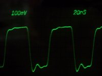
Bernhard said:Is this normal ?
Output of my Kwak clock.
Probe is adjusted 1:10.
Why are ferrite beads so important ?
Instead I used 470µH from Philips CD output filter and 220µF Oscon.
Bypassing doesn't help.
Also tried other decoupling.
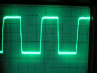
Hi
I wonder why these clocks loo so scary ?
Attached is one of my product range, same timebase (20ns/div)
cheers
Attachments
- Status
- This old topic is closed. If you want to reopen this topic, contact a moderator using the "Report Post" button.
- Home
- Source & Line
- Digital Source
- Problem with Kwak Clock power supply