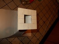
You don't want it too small or it won't be able to reach the lower frequencies as well and you may have resonances and a constricted sound. I made a box that goes around driver, circa 2.4 liters and lined with foam.
Is that low frequenties I thought 400 hz not depended of horn cutoff itselfs? I do mean the small driver on throat not the bas units who go to 80 hz.
I dit thought it needs small, I have simulate but I see not much invloence on changing chamber. my speaker is also smaller, maybe I can sim a closed box to see what it does, so that it reach the horn low cutoff.
regards
If the rear chamber is of same order as the Vas or 1/2Vas you are good. That is just to match the compliance because if volume is much smaller than Vas, air acts as a stiff spring and fs is higher and low freq corner will be higher.
Thanks, Vas is 1.1 liter, so I can use 0.55 to 1.1 liter. I do use 1 liter because 0.55 dit give some little peaks, 1.5 liter is some more did even some better. I can sim a closed box and see how much Fs do rise.
Can you explane for akabak how to use the injection ports, how to move them? thanks.
regards
kees
Last edited:
Those look nice, you gotta love that sensitivity for 2,83v. Be careful when testing - you can hurt your ears as it is loud but so clean and low distortion you won't it.
The all pass delay filter is how I effect the delays, is that how you do it?
Yes I did use the delays to make it like it is, but without it is also really suprising good. using a correction in the woofer section will get it as good as with delay and it
is a lot easy to do with notch circuits..
By the way here some good calc stuff.
http://www.mh-audio.nl/spk_calc.asp
Attachments
Last edited:
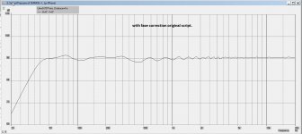
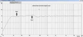
I have also try your original script with and without fase correction, very much differents I do not see, but small ones can alsready impact the sound I think fase liniair is very important for smood sound special with high efficienty speakers.
regards
regards
Attachments
Last edited:
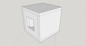
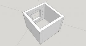
This is the way I go make that box, I need to cut 0,9 cm from the throat because otherwise the throat get smaller I put thare extra 0,9 cm for baffle for speaker not much but I want to keep the sim outcome intact.
regards
regards
Attachments
I did discover that the length of the horn is 5mm longer, I do not now yet if it is react different on that, I think not because it is so little, but it is th throat so maybe I am wrong.
Where can I find the bas injection ports setup in akabak< maybe a snippet from script can help me, I am not wel educated with akabak .
I have tryed some sound without a box behind the speaker but then it sounds not very wel, little strange sound, not loud also.
Thanks.
regards
Where can I find the bas injection ports setup in akabak< maybe a snippet from script can help me, I am not wel educated with akabak .
I have tryed some sound without a box behind the speaker but then it sounds not very wel, little strange sound, not loud also.
Thanks.
regards
Last edited:
Where can I find the bas injection ports setup in akabak< maybe a snippet from script can help me, I am not wel educated with akabak .
You just presented sims of the mids and highs in the previous post so I assume you know where that is located in the code, otherwise, how did you sim the mid? The mids is the same as bass injection ports in a Trynergy FAST. For below 80Hz I used a separate FLH sub script.
You just presented sims of the mids and highs in the previous post so I assume you know where that is located in the code, otherwise, how did you sim the mid? The mids is the same as bass injection ports in a Trynergy FAST. For below 80Hz I used a separate FLH sub script.
Hi
Yes some learning I did, I have disable the tapped horn, that is not difficult as it shows themselfs, I have also did input my horn dimensions, but left the input ports as it is, and put in my speaker parameters. But do not now how to move the ports of the bass unit there, so some explaining will do I think.
I have input the script so you can see it yourselfs.
thanks.
kees
Attachments
Hi
Yes some learning I did, I have disable the tapped horn, that is not difficult as it shows themselfs, I have also did input my horn dimensions, but left the input ports as it is, and put in my speaker parameters. But do not now how to move the ports of the bass unit there, so some explaining will do I think.
I have input the script so you can see it yourselfs.
thanks.
kees
The horn profile is defined by many segments, each one with a starting and end node. If you specify the node of the injection port to be the same as one of the nodes of the horn segment, you basically have connected the injection port to that segment and the acoustical energy will "flow" or be injected at the point. For this horn, the mid injection port happens between segments 6/7 on node=57. I have added a | #### at the relevant points in the code to focus your attention. If you want to move the port farther down then change the node on the injection port to be a larger number, say 62 etc.
In the snippet of the code below, node=x=y means x (node 111) is the node of the driver duct connected to chamber formed by diaphragm and y (node 5) is the point on horn wall where duct is connected.
Code:
| *** duct from driver 1 compression chamber to horn injection point ***
Duct    'Inject Port 1'  Node=111=57  | #### node 57 is where injection port is located, move node number if you want a differnet location
    dD={Dia_inj}  Len=0.719in | Thickness of wall plywood
Attachments
The horn profile is defined by many segments, each one with a starting and end node. If you specify the node of the injection port to be the same as one of the nodes of the horn segment, you basically have connected the injection port to that segment and the acoustical energy will "flow" or be injected at the point. For this horn, the mid injection port happens between segments 6/7 on node=57. I have added a | #### at the relevant points in the code to focus your attention. If you want to move the port farther down then change the node on the injection port to be a larger number, say 62 etc.
In the snippet of the code below, node=x=y means x (node 111) is the node of the driver duct connected to chamber formed by diaphragm and y (node 5) is the point on horn wall where duct is connected.
Code:| *** duct from driver 1 compression chamber to horn injection point *** Duct 'Inject Port 1' Node=111=57 | #### node 57 is where injection port is located, move node number if you want a differnet location dD={Dia_inj} Len=0.719in | Thickness of wall plywood
Hi
Then I think I was already on the good path, thanks for your explaning about it, I go sim, without delays, put these 0, and first try to get best respons and then flatten it with delay input, if I am right to do this that way, so I can see what the ports do without impact of the delay effect.
I have made the little box, it is 0.8 liters big, I need to stuff it heavenly I did read, so these weekend I go measure the stuff without the bass unit, that is later on.
I I live then because in Syria it get dangerous.
regards
kees
Attachments
Tested,, I presume you use two woofers like me? in your case 12 inchers, I do use 8 inchers, I have therefore need two changes, Now find the bassreflex inputs and I am ready to test the stuff in akabak, Now I think I get where I want to be.
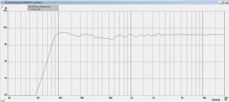
Moving the ports to 72 did change a lot, as a test afcourse, then I did manipulate the delay and get this graph. efficienty did rise also some dB.
thanks.
kees
Moving the ports to 72 did change a lot, as a test afcourse, then I did manipulate the delay and get this graph. efficienty did rise also some dB.
thanks.
kees
Attachments
Tested,, I presume you use two woofers like me? in your case 12 inchers, I do use 8 inchers, I have therefore need two changes, Now find the bassreflex inputs and I am ready to test the stuff in akabak, Now I think I get where I want to be.
Moving the ports to 72 did change a lot, as a test afcourse, then I did manipulate the delay and get this graph. efficienty did rise also some dB.
thanks.
kees
I used four 6.5in woofers. Your build looks good. Does it sound better with rear sealed chamber?
I used four 6.5in woofers. Your build looks good. Does it sound better with rear sealed chamber?
Not yet tested, glue has to dry, but yours are also closed or not? because you ask that, it is in script also as far as I did see.
put the speaker on the horn without chamber let him get not very high, and efficienty low was mine thought when trying it the fast way
regards
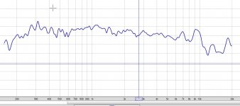
Did some measurements in house, so room is involved, I need go get long cable for outside.
This is what comes out. I did use REM and holmimpulse for the tests, but need a mic amp, I have build one in past, I go put it tegether because I did measure with the mic input of the pc what is not really oke I think.
The mic amp do better I hope with the burr brown opamps.
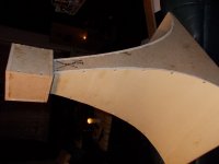
Picture two looks very nice, close to horn, think so 25 cm.
regards
This is what comes out. I did use REM and holmimpulse for the tests, but need a mic amp, I have build one in past, I go put it tegether because I did measure with the mic input of the pc what is not really oke I think.
The mic amp do better I hope with the burr brown opamps.
Picture two looks very nice, close to horn, think so 25 cm.
regards
Attachments
Last edited:
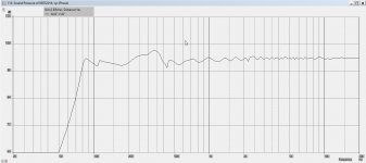
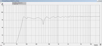
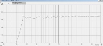
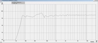
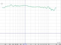
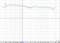
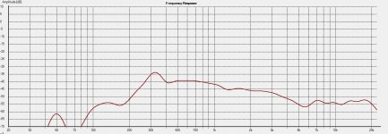
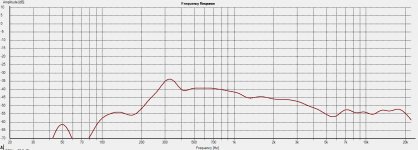
And here the speaker from visaton and the phillips in free air first is phillips and second visaton..
looks like wild impedances need correction. post 557 I did let see different tests with two programs and plots from different places in room and distance.
looks like wild impedances need correction. post 557 I did let see different tests with two programs and plots from different places in room and distance.
Attachments
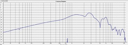
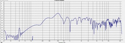
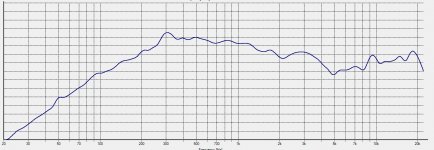
did measurement 1 meter distance with and without chamber, not much differents but is looks like this speaker do not well or horn is wrong.
It go down after 5 Khz after that it looks very good for me, but 15 dB down can be not easy corrected, so I go first make the mic amp ready and maybe the visaton cone do break up very fast like 5 Khz.
I can hear also mids are louder then hhe high give some hollowlike sound.
How do you did the throat? just a square or did you that different, I thought you have just a square.
regards kees
Attachments
Last edited:
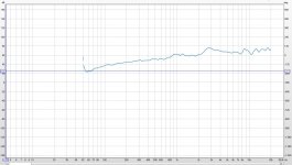
I used a square throat. It is very important that the throat is smooth with no rough edges. Make sure you have a space to keep the driver cone or surround from touching the throat on outward extension. There is a normal dip usually around 4.5k. It is natural for a driver to have a power response falloff about 10 to 12 dB from 5k to 20k. I forget what mine was but that is where DSP EQ comes in handy. A simple high shelf negates that and as it is a rising in frequency response you don't have to worry about over excursion. Look at my plots before and after EQ to get an idea. It is important to get a driver with a powerful motor. The Faital 3FE22 was better than the TC9FD for this reason. It has enough power to let you EQ boost the HF.
I can't tell what your vertical scale is. In REW there is a snapshot feature in upper left Corner of plot box. Click that and generate PNG file of plot with axis labels. Otherwise I can't tell what SPL levels you have and what frequency.
I can't tell what your vertical scale is. In REW there is a snapshot feature in upper left Corner of plot box. Click that and generate PNG file of plot with axis labels. Otherwise I can't tell what SPL levels you have and what frequency.
- Home
- Loudspeakers
- Multi-Way
- Presenting the Trynergy - a full range tractrix synergy.