Here is a link to a directivity controlled in room impulse plot from my system.Something I would love to see is a real-life comparison of time (impulse) and frequency measurements taken in an actual listening room with directivity-controlling speakers, and traditional speakers.
Thanks for the inputs so far!
They do tend to get long and difficult to terminate.some limiting factor that prevents narrowing vertical dispersion beyond the 40 degree mark,
They can be made in the shape of a spherical cap, rather than a line to control both directions. Their behaviour then resembles that of a horn.Regarding the Keele CBTs, those have typically been created with a wide dispersion characteristic, which is again at odds with what I think I want.
KEF have recently released a white paper on their Reference series. Although it talks a lot about their UniQ driver and waveguide approach, it does have some useful information on ideal directivity and room interaction. They seem to have done a lot of measurement work on it.
It's a PDF download from here
http://www.kef.com/uploads/files/THE_REFERENCE/REF_White_Paper_preview_path_200514.pdf
Hope it proves of interest.
It's a PDF download from here
http://www.kef.com/uploads/files/THE_REFERENCE/REF_White_Paper_preview_path_200514.pdf
Hope it proves of interest.
I've done a bit of work on the lower treble region. I'm trying to extend the nulls between 20 and 40 degrees to cover as much bandwidth as possible. I think this is a significant improvement from yesterday. The plots are symmetric, so I'm not going to bother showing both halves. For reference, 200 = 322 hz, 250 = 1367 hz, 300 = 5792 hz.
I've reread your original post and understand what you are trying to do. I did the same geometrical analysis of my room and sitting position and found that with my waveguides and within their control frequency limits, the ceiling bounce would fly over my head but the floor bounce would hit me in the face.
Thus, I can see the benefit of being able to aim a null at the floor halfway between my listening position and the speaker and I'm impressed at your ability to do that over a wide band instead of just around a crossover point. As to the BW of these nulls, it seems the upper limit would be determined by where the carpet and pad provide enough absorption.
I have been resigned to needing ceiling treatment and, ultimately it may be the easiest (although least elegant) way to deal with low frequency ceiling reflections. Waveguides that would do it much below 1 Khz are impractical. A Snell Expanding array gets to be imposingly tall. But I have open attic space above my room so could add as much absorption as needed if my wife lets me remove the sheetrock.
You haven't provided much detail about what it takes to implement the beam steering that you are simulating. I would find that very interesting. Is the vertical beam steering technique compatible with controlled horizontal directivity?
Last edited:
I've reread your original post and understand what you are trying to do. I did the same geometrical analysis of my room and sitting position and found that with my waveguides and within their control frequency limits, the ceiling bounce would fly over my head but the floor bounce would hit me in the face.
Thus, I can see the benefit of being able to aim a null at the floor halfway between my listening position and the speaker and I'm impressed at your ability to do that over a wide band instead of just around a crossover point. As to the BW of these nulls, it seems the upper limit would be determined by where the carpet and pad provide enough absorption.
I have been resigned to needing ceiling treatment and, ultimately it may be the easiest (although least elegant) way to deal with low frequency ceiling reflections. Waveguides that would do it much below 1 Khz are impractical. A Snell Expanding array gets to be imposingly tall. But I have open attic space above my room so could add as much absorption as needed if my wife lets me remove the sheetrock.
You haven't provided much detail about what it takes to implement the beam steering that you are simulating. I would find that very interesting. Is the vertical beam steering technique compatible with controlled horizontal directivity?
Thanks for the input, and consideration of this technique. I don't think it's compatible with waveguides, though, as they increase driver spacing.
Until last night, I had been attempting to skip directly to the design phase of my next speaker. I had chosen drivers to use, obtained zma and frd files, simulated crossovers, etc. Everything I posted was the result of applying actual crossover topologies to actual drivers. Nothing was theoretical about it, but it turns out I need to develop the theory more, which became apparent working within the limited capacity of the drivers I had chosen. ( I am admittedly rushed because when my kids go back to school at the end of summer, time for cutting wood will once again disappear from my schedule.)
Last night I scrapped all that and developed a generic, theoretical simulation for speakers in a vertical line, with varying crossover points and placement. I quickly confirmed a suspicion I had been forming: The 30 degree null can be accomplished by roughly copying the Snell Expanding array concept, but doubling the inter-driver spacing.
There may be other ways to accomplish it, but that approach works very well (at least in theoretical simulations):
Nested drivers symmetrically placed on a baffle, with spacing that decreases as frequency increases, and 2nd order crossovers between neighbors.
I haven't figured out yet exactly what limits the frequency separation between one set of drivers and the next, but if you try to jump too much bandwidth, you'll lose your null. Also, if you apply higher order crossovers, you'll get modulation of your mainlobe, as it grows and shrinks at different frequencies.
So you might end up with a W-M-T-ST-T-M-W, or even a SW-W-M-T-ST-T-M-W-SW, where SW = subwoofer and ST = super tweeter.
Having said that, it may not be practical to address the lower frequencies using this method, and something like an M-T-ST-T-M paired with multiple subwoofers may be preferred.
I can post theoretical plots, and include the source code for anyone interested in running it or playing with it. It should work in Octave or Matlab. Hopefully I can do that tonight, or at least before the weekend is over.
It was interesting to apply a simple scalar to all the driver spacings:
My original approach yielded a 30 degree null.
Divide all the driver spacings by 2, gave me the 90 degree null of the eXpanding arrays.
Something in between, 0.707 looked promising as well.
Admittedly, the driver spacing of the eXpanding arrays is very difficult to reproduce, so it would be a welcome change to be able to work with a greater spacing.
Last edited:
Along the same vein, If you look at the graphs in D'Appolitos Geometrical Approach... (MTM paper), you will see the control of the vertical beam holding at crossover and somewhere between 1 and 2 octaves below. I've played with XDIR to see the same thing and experiment with different spacings. Extending this to multiple ways to cover those 1 or 2 octave regions sounds quite reasonable.
I've been asking myself why not a waveguide at the middle of such a stack? but so far have settled for a midbass module just below the waveguide and hoping that room treatments would make up for its shortcomings.
Also Don Keele did a paper in which derived a new DSP crossover topology for similar speakers. "Application of Linear-Phase Digital Crossover Filters to Pair-Wise Symmetric Multi-Way Loudspeakers" which you can find here
AES Papers -- Official website of D.B.Keele
Is it "GNU OCTAVE" you are using? I will have to look into that and see if I can revive long unused math and programming skills.
Did you not mean it would be welcome to work with lesser spacings?
Thanks nc535, for the links.
I am using GNU Octave.
Regarding the driver spacing: increased inter-driver spacing is welcome at high frequencies, where it's almost impossible to get the drivers close enough together. You are right that at low frequencies, decreased driver spacing would be welcomed, because the arrays get tall.
I am using GNU Octave.
Regarding the driver spacing: increased inter-driver spacing is welcome at high frequencies, where it's almost impossible to get the drivers close enough together. You are right that at low frequencies, decreased driver spacing would be welcomed, because the arrays get tall.
I still find it odd that the thread itself poses the question of preferred/ideal directivity, yet never really broaches the subject; instead moving on as if controlled directivity in any form is somehow superior.
I share this sentiment in many respects. However, I don't think it's that odd to figure out your options even if you don't know what one you'll ultimately prefer.
If nothing else, it makes it easier to experiment, right?
I share this sentiment in many respects. However, I don't think it's that odd to figure out your options even if you don't know what one you'll ultimately prefer.
If nothing else, it makes it easier to experiment, right?
As a design challenge it's excellent!
")
-beyond that however it's largely misguided.
A good design looks for linear downward sloping freq. response at the listener position (and actually several positions around the listener) - basically flat, but about 2 to 4 db down from 100 Hz to 20 kHz (depending on the particular listener's preference).
Usually the only real impediment to this is from floor bounce effects (and to a lesser extent ceiling effects), and modal effects.
Both can be "engineered" around to a large extent.
For floor/ceiling bounce just use a bounding (to the floor) line of drivers covering frequencies below about 450 Hz. (..usually 4 drivers). It should be a steep filter for the 450 to 500 Hz range for the crossover.
Ex. Boston Acoustics M350 loudspeaker
Boston Acoustics M350 loudspeaker Measurements | Stereophile.com
Note that the midrange crossover was too low in freq. at 280 Hz (fig. 3) relative to its in-room response (fig. 6).. and of course the baffle-step correction was too strong at 100 Hz.
For modal effects: add more sources within the modal range fairly "randomly" (and adjust for phase/time & level & low-pass filter).
Last edited:
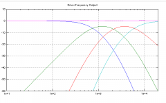
Here's the update with the theoretical stuff, ignoring actual driver limitations of all kinds.
Simulated as follows:
Crossover frequencies = 750, 2140, 6000
Driver Vertical Positions (inches) = +/-18, +/-6.33, +/-2.25, 0
No Baffles, No wall reflections, etc.
The driver frequency response graph shows relative outputs for pairs. The tweeter doesn't have a match, but it needs to match the relative levels of the other pairs (summed). So the tweeter needs to reach the shown level by itself, while all the other speakers rely on a partner to help reach the level shown.
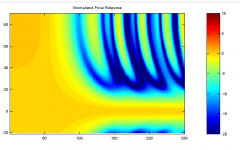
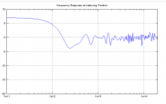
Also, I didn't want to complicate things to add tweeter directionality, nor did I want to show a polar response that transitioned to omnidirectional at the highest frequencies, so I added a pretend crossover to a supertweeter at 20K for the polar and listener position frequency response graphs below. This listener position plot only takes into account the first floor and ceiling reflections: no walls, no higher order reflections. It's just a representation of how well the first vertical reflections could have been mitigated.
On the polar plot, 100 = 205 Hz, 150 = 945 Hz, 200 = 4347 Hz.
The source code wont upload with a .m extension, so I gave it a .txt extension. It should accept any number of crossovers more than 0. Also, a parameter was included to scale the driver spacing.
Simulated as follows:
Crossover frequencies = 750, 2140, 6000
Driver Vertical Positions (inches) = +/-18, +/-6.33, +/-2.25, 0
No Baffles, No wall reflections, etc.
The driver frequency response graph shows relative outputs for pairs. The tweeter doesn't have a match, but it needs to match the relative levels of the other pairs (summed). So the tweeter needs to reach the shown level by itself, while all the other speakers rely on a partner to help reach the level shown.
Also, I didn't want to complicate things to add tweeter directionality, nor did I want to show a polar response that transitioned to omnidirectional at the highest frequencies, so I added a pretend crossover to a supertweeter at 20K for the polar and listener position frequency response graphs below. This listener position plot only takes into account the first floor and ceiling reflections: no walls, no higher order reflections. It's just a representation of how well the first vertical reflections could have been mitigated.
On the polar plot, 100 = 205 Hz, 150 = 945 Hz, 200 = 4347 Hz.
The source code wont upload with a .m extension, so I gave it a .txt extension. It should accept any number of crossovers more than 0. Also, a parameter was included to scale the driver spacing.
Attachments
Last edited:
Here's an exmple of directivity control with extra speakers and DSP filters.
acoustics
Thanks for the link.....that's interesting. A quadrupole?
I still find it odd that the thread itself poses the question of preferred/ideal directivity, yet never really broaches the subject; instead moving on as if controlled directivity in any form is somehow superior.
Wasn't this discussed at great length, with no real consensus, in keyser's "What is the ideal directivity for stereo loudspeakers" (or whatever it's called) thread?
For instance, most waveguides available are too wide vertically to drastically reduce floor and ceiling reflections: they would need to have a vertical response limited to less than 40 degrees (at least in my listening room with my seating position). Also, waveguides for low frequencies get large, making it difficult to create multi-way speakers without very large center to center spacing, which creates lobing issues. Of course, there's distortion concerns as well. Personally I have yet to hear a horn or waveguide speaker that doesn't offend my ears, though I admittedly haven't heard too many. I can't DIY arbitrary shapes for waveguides, and I can't find pre-fabricated ones that will do what I want them to do. For all these reasons, I find it very unlikely that I'll use a waveguide to address this issue.
Instead, I plan to address it using multiple drivers by applying beamforming techniques. Specifically, the idealized version of what I would like to do amounts to a null-steering beamformer.
<SNIP>
I could apply what I've done and build a speaker, but I don't have time to build and rebuild as I learn / improve, so I want to do it right the first time.
Thoughts?
As far as the build/rebuild issues....this design is complicated enough where to get the absolute best possible result I would think at least a few prototypes would be required.
For the horns, and waveguides....I *highly* suggest you re-examine the possibility of a DIY Synergy horn. I've now built three prototypes, and two complete horn systems using Danley's design theories. Synergy's have been mentioned in this thread a couple of times....but not in any serious way.
They provide the ability to eliminate the lobing issues all drivers use the same wave guide. If 40 degrees is your desired vertical dispersion limit, 40x60 or 40x75 would be possible and still provide reasonable horizontal coverage areas.
Mine are 60x60 (22x22 inch mouth, good directivity to ~600Hz) and 50x50 (16x16 inch mouth, good directivity to ~1kHz)
They provide imaging that is beyond anything I've ever heard, with only the large planer speakers coming close. I've actually had people get up and stick their head in my center channel horn because they don't believe it's off....that's how solid a center image is once you remove those reflections.
The overall sound of the speakers are essentially the best combination of horns, headphones, ribbons, and electrostatics. The only draw-back I see is the SAF of a boxy large speaker. Arraying speakers isn't small either though....
Edit: Link to DIYAudio thread of my 60x60 Synergy Horns.....http://www.diyaudio.com/forums/multi-way/244890-synergy-horns-dayton-prv.html
Scott
Last edited:
Hi Speaker Scott:
I followed your design and I'm on the 2nd proto of my own Synergy. I know you know how long it takes to refine these things.
Do you find floor or ceiling bounce to be an issue in room and have you done anything in the way of treatment to mitigate them. As I recall yours are close to the floor to minimize floor bounce or perhaps push it up to where carpet will absorb it.
Hi Speaker Scott:
I followed your design and I'm on the 2nd proto of my own Synergy. I know you know how long it takes to refine these things.
Do you find floor or ceiling bounce to be an issue in room and have you done anything in the way of treatment to mitigate them. As I recall yours are close to the floor to minimize floor bounce or perhaps push it up to where carpet will absorb it.
Yeah, mine are close to the floor, angled up at about 15 degrees. The carpet is of minimal help, it's not very thick. Ceiling bounce lands behind the primary seated listening position, as do sidewall bounces. I angle them in so that the outside edge is parallel to the wall meaning that the sidewall bounce is from the opposite side speaker. Giving it plenty of time and distance to dissipate. In room measurements are remarkably flat and similar to groundplane.
Scott
The driver frequency response graph shows relative outputs for pairs. The tweeter doesn't have a match, but it needs to match the relative levels of the other pairs (summed).
Are the drivers paired vertically above and below the tweeter?bbutterfield said:This listener position plot only takes into account the first floor and ceiling reflections
The comb filtering at fixed wider angles that could be caused by the distance from each driver in a pair swinging in and out of phase with frequency. If you want, this is ok as a way to effect directivity but you may need closer spacing within a pair. You can use more than two of each driver to extend the array length for lower frequencies. The floor and ceiling will mirror the length if you locate the woofers within range.
On the polar plot..
You could use an absorptive waveguide to help clean up the vertical combing "trails" that are near the pressure average.. a'la Duntech/Dunlavey & Lipinski.
Attachments
Wasn't this discussed at great length, with no real consensus, in keyser's "What is the ideal directivity for stereo loudspeakers" (or whatever it's called) thread?
True, and a great many others as well.
I'm not particularly concerned by the lack of the discussion (..though it is kind of a "click-bait" title), but rather the onward progression as if enhanced vertical directivity was implicitly required to achieve better sound, particularly when most objective sources would argue otherwise.
But like I said before - it still an interesting design challenge (and implementation) that the thread poster has presented.
Here's another vote for a Synergy design. At least in my case, how the speaker sounds when I'm NOT in the sweet seat also affects how well the illusion works. Nothing more artificial (to me at least) than having the sound go flat or swim around when you stand up or move a little, and you really can't turn off that subjective effect via mind control. Synergy horns sound like musicians are there even when you get up to go get a beer!
BTW, I think I remember some reference earlier it the thread to steering a CTC cancellation null at the floor to avoid reflections? I see this mentioned at times, but I doubt the null can be used as an advantageous thing like this -- it isn't very wide in frequency range, so it would work only over a small band. In other words, the null is wide enough to be a problem but too narrow to be used as a source of much directivity.
BTW, I think I remember some reference earlier it the thread to steering a CTC cancellation null at the floor to avoid reflections? I see this mentioned at times, but I doubt the null can be used as an advantageous thing like this -- it isn't very wide in frequency range, so it would work only over a small band. In other words, the null is wide enough to be a problem but too narrow to be used as a source of much directivity.
- Status
- This old topic is closed. If you want to reopen this topic, contact a moderator using the "Report Post" button.
- Home
- Loudspeakers
- Multi-Way
- Preferred / Ideal Directionality