Looking into several of the "el cheapo" single coil pickups from China and surplus outlets. Other then subjectively making temporary mounting on or over strings on a real guitar with an amplifier and just listening, is there some way to set up a test based more on measurements? I realize any such test would still be subjective, but maybe it would still be helpful for comparison? Maybe a frequency sweep from a signal generator into the pickup, with a series resistor, noting where the impedance peak(s) occur? Just grasping at straws here.
Hi,
Yes indeed. Simply put hotter pickups have more inductance and
roll off lower than lower output pickups. So coil inductance is a
good clue as to the likely output level and amount of topend.
(Unless of course the coils have **** poor quality magnets.)
However guitar tone controls have capacitors that resonate
with the coils and again the lower the inductance the higher
the frequency will be, maybe that will be not you want, you
have to test in the guitar.
Your best bet for comparing a bunch of similar looking
single coils is measuring the DCR and the inductance.
rgds, sreten.
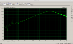
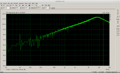
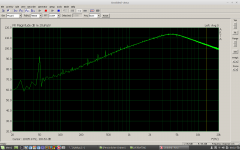
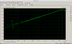
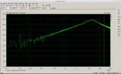
Yes, the wiring alters the resonance peak, normally to a lower frequnency. You can measure the pickup w/o wiring using a PC, soundcard and ARTA for comparision.
I appended some plots made this way in the order
DiMarzio humbucker
Riverhead single coil
Seymor Duncan humbucker
Tesla stacked humbucker
Ultrasonic stacked humbucker
You can see there are big differences of the unloaded pickups
I appended some plots made this way in the order
DiMarzio humbucker
Riverhead single coil
Seymor Duncan humbucker
Tesla stacked humbucker
Ultrasonic stacked humbucker
You can see there are big differences of the unloaded pickups
Attachments
Last edited:
Hi,
Yes indeed. Simply put hotter pickups have more inductance and
roll off lower than lower output pickups. So coil inductance is a
good clue as to the likely output level and amount of topend.
(Unless of course the coils have **** poor quality magnets.)
However guitar tone controls have capacitors that resonate
with the coils and again the lower the inductance the higher
the frequency will be, maybe that will be not you want, you
have to test in the guitar.
Your best bet for comparing a bunch of similar looking
single coils is measuring the DCR and the inductance.
rgds, sreten.
Very interesting! This is actually part of a home brewed travel guitar I've designed, which uses a magnetic pickup, but has an active pre-amp circuit. The pre-amp maintains what i believed to be the most common pickup load, of 500K, and the next stage is a +/- 20dB active boost/cut treble contro, cornering at about 1kHz. It sounded great with my first single coil pickup, which was a "one of a kind" I've had floating around forever. But when i tried some of my cheap pickups I was shocked. If anything i'd have thought they would lack bass. The bottom end was fine, but when i advanced my EQ, I almost thought the circuit had failed! The sad reality was, you can't amplify treble that doesn't exist.
So you're saying, first measure inductance. Would the readings form an ordinary "LC" meter be useful at all, considering there is probably coil resistance affecting the measurement? Also, when you say "DCR", I imagine this means coil resistance? So would higher values be better for high end, or lower values? And finally, I'm very sure these pickups have "cheap" magnets. So are you saying stronger magnets increase hige ned, or the opposite?
Thanks tfor the insight!
Yes, the wiring alters the resonance peak, normally to a lower frequnency. You can measure the pickup w/o wiring using a PC, soundcard and ARTA for comparision.
I appended some plots made this way in the order
DiMarzio humbucker
Riverhead single coil
Seymor Duncan humbucker
Tesla stacked humbucker
Ultrasonic stacked humbucker
You can see there are big differences of the unloaded pickups
Not sure what software or external equipment you're connecting there, or what an ARTA is. But I like the idea of seeing the result visually. What i do have is (1) a sine wave frequency sweeper (something I actually called "ART", short for "Audio Response tester" in an article I wrote for Popular Electronics, some 30 years ago!). And I have a scope. The frequency sweeper has its own ramp output to control the horizontal on a scope, while the sine wave output does a logarithmic sweep, approx from 20 - 20Khz. I built that thing mainly for testing the response of amplifiers and audio filters, but I'm not sure exactly how I would hook it up to a pickup. If you shared with me more details of the connections you made for the setup you described, maybe I can duplicate it with the equipment I have. As for my PC, I have a good quality sound card, but its an old XP-Pro system, and I don't know if the software in your pictures would run on it.
thanks for the info!!!
You can use your signal generator and scope. The signal level maybe several Vpp, coupled via 1meg resistor to the hot terminal of your pickup. Measure the level with your scope using a 10:1 probe (10meg input resistance). In that case you pu is damped by about 900kOhm, that is sufficient for the test.
You will find that the pickups with lowest DC-resistance of the coil have lowest inductivity, and thus the peak resonance frequency is the highest. I can say that any pickups with a peak below 3.5khz sound dull to me - I like the crisp fender treble.
ARTA is a (R)eal(T)ime (A)nalyser software you can download for free that works on Linux, Mac and even Win.
I do my measurements simply with the mic input of my Laptop (lenove X201) connected via 1meg series resistor to the hot terminal of pu, and the headphone output is coupled to the same point via another 1meg series resistor. Output volume is set to 100%. And thats all!
For a better noise performance, a source JFET-follower or any buffer amp should be inserted between PU and mic input, saving the noise contribution of 1meg series resistor.
Last edited:
Well thanks everyone! And I'm definitely going to look for this ARTA software! There seems to be some conflict of opinions here, where sreten said "hotter pickups have more inductance and roll off lower than lower output pickups", while voltwide seemed to say the opposite: "pickups with lowest DC-resistance of the coil have lowest inductivity, and thus the peak resonance frequency is the highest". I guess I'll find out for myself as i run some tests.
Bottom line though, I'm actually a little worried I will find that indeed all these pickups $5 and less on ebay or ali-express are simply not going to have much high end at all. Its worrisome when you're hoping to make a product. When something is "one off", and just for your own use, its easier to justify spending retail prices for the best pickups you can afford. But when you're trying to make a cost effective product, high ticket components make the whole project less affordable, and its unlikely I'll find a bargain on a bulk order of pickups. So I may have to ask for some recommendations here. Seeing that $2 single coil pickups are all likely duds, is there any hope I can do better with, say, $20 pickups? If not, I just may have to start learning to wind my own!
Bottom line though, I'm actually a little worried I will find that indeed all these pickups $5 and less on ebay or ali-express are simply not going to have much high end at all. Its worrisome when you're hoping to make a product. When something is "one off", and just for your own use, its easier to justify spending retail prices for the best pickups you can afford. But when you're trying to make a cost effective product, high ticket components make the whole project less affordable, and its unlikely I'll find a bargain on a bulk order of pickups. So I may have to ask for some recommendations here. Seeing that $2 single coil pickups are all likely duds, is there any hope I can do better with, say, $20 pickups? If not, I just may have to start learning to wind my own!
I made some measurements on a couple of guitar pickups a few years ago. Faced with the same problem you have, my solution was to make a test coil, and feed it from the audio signal generator.I'm not sure exactly how I would hook it up to a pickup.
The test coil creates a weak audio magnetic field; place it on top of the guitar pickup under test, and the guitar pickup will do what it's designed to do - generate a voltage induced by the AC magnetic field. You can now make your frequency response sweep measurements.
For the test coil, I found that something like a hundred turns of 36 gauge enameled copper wire, wired on a former roughly the same size and shape as a single-coil bobbin in a Fender pickup, worked very well.
With the test coil made, you feed it from your audio oscillator, via a series resistor, to make sure you have constant current drive. The series resistance needs to be high enough to swamp out any inductive impedance of the test coil, even at the highest frequency you measure at. (1k ohm worked for me; yes, it only takes a couple of milliamps of AC current in the coil.)
Now place the test coil near the pickup, and measure away!
For what it's worth, I got nonsensical results until I connected a guitar cable to the pickup. The pickup on it's own has a self-resonant frequency, which is usually up around 5-7 kHz - well outside the guitar bandwidth, and therefore pretty much inaudible through a guitar amp.
That changes when you connect the usual 10 ft or 15 ft guitar cable to the pickup. At around 30 pF per foot, that's 300 to 450 pF of capacitive loading. Enough to create a new resonant frequency, this time within the guitar bandwidth. I think this is the one that actually matters - and it is very heavily dependent of the guitar cable, not just the pickup!
-Gnobuddy
Mathematically, the number of coils is directly proportional to the amount of current (and therefore voltage) and inductance of a coil (if all other factors are constant). In other words, more coils = hotter and lower resonant frequency f=1/(2pi*sqrt(LC)) where L is inductance and C is capacitance.Well thanks everyone! And I'm definitely going to look for this ARTA software! There seems to be some conflict of opinions here, where sreten said "hotter pickups have more inductance and roll off lower than lower output pickups", while voltwide seemed to say the opposite: "pickups with lowest DC-resistance of the coil have lowest inductivity, and thus the peak resonance frequency is the highest".
There is no conflict, both statements tell the sameThere seems to be some conflict of opinions here, where sreten said "hotter pickups have more inductance and roll off lower than lower output pickups", while voltwide seemed to say the opposite: "pickups with lowest DC-resistance of the coil have lowest inductivity, and thus the peak resonance frequency is the highest". I guess I'll find out for myself as i run some tests.
")
I made some measurements on a couple of guitar pickups a few years ago. Faced with the same problem you have, my solution was to make a test coil, and feed it from the audio signal generator.
The test coil creates a weak audio magnetic field; place it on top of the guitar pickup under test, and the guitar pickup will do what it's designed to do - generate a voltage induced by the AC magnetic field. You can now make your frequency response sweep measurements.
-Gnobuddy
Interesting. Thanks. In my case, the pickup will always see a constant load of around 400K... basically a 500K pot. the wiper of the pot isthen it is fed through a capacitor directly to an OP-AMP, with a small series resistance, and a 1mg resistor to ground on the OP-AMP input. So worst case (pot set to max), the pickup will see 500K in parallel with 1meg. What i'm saying is, there will never be an additional loading affect caused by a cable.
Interesting approach though! I'd be a little concerned my "test coil" would add some of its own characteristics.
This could happen indeed. I think direct coupling the signal with some resistor is more straightforward way.Interesting approach though! I'd be a little concerned my "test coil" would add some of its own characteristics.
Yes, the wiring alters the resonance peak, normally to a lower frequnency. You can measure the pickup w/o wiring using a PC, soundcard and ARTA for comparision.
You can see there are big differences of the unloaded pickups
Please help me understand what you're doing here with this software, because I downloaded it and I'd really like to start using it. Up to now, I've been using a home brewed frequency sweeper that also drives the horizontal input of a scope, leaving the vertical to measure the response through a device, as the frequency continuously sweeps from 20hz to 20K. Now in ARTA, the only similar function i see is called "Impulse response Measurement", and it doesn't repeat automatically, you have to trigger it with a "RECORD" button each time. Is that what you used?
I see they also have white and pink noise generators, which seem to be the prefered way of measuring / building a frequency response graph. It THAT what you did to get the plots you posted? I would have though that such a dense multi frequency signal would risk saturation and skew the results. But maybe I'm thinking old school. I have to admit the math explained in the user manual is beyond me. Its been MANY years since I had to deal with analysis formulas like that, and I'm still shocked I passed some of those courses.
That probably means your pickups will sound pretty different from the way they do in a conventional guitar, where there is no on-board preamp. (That's not a judgment, just an observation.)In my case, the pickup will always see a constant load of around 400K...
I had the same concern. You may have noticed I took some steps to reduce this possibility: I wound a very small number of turns to create negligible inductive reactance within the guitar's frequency range, and I used a series resistor to ensure constant current drive to the coil. (This means the strength of the current into the coil won't fall as the frequency rises.)I'd be a little concerned my "test coil" would add some of its own characteristics.
The other thing you have to do is make sure the test-coil doesn't move relative to the pickup under test. I just use some 3M painters masking tape to tape the test coil in place during testing.
If you know your Maxwell's equations (electromagnetism), a constant current sine wave into a coil will generate a magnetic field whose rate of change is directly proportional to frequency.
This is exactly what you expect from vibrating a small piece of magnetic material (the guitar string) near a pickup polepiece. There too, the rate of change of magnetic flux will be directly proportional to the frequency of vibration, all else being the same.
In other words, what the test coil does is give you a way to duplicate what a vibrating guitar string does to the pickup - but in a very precise and controllable way. It lets you measure what a pickup actually does in a functioning guitar.
The other method mentioned here - directly measuring the impedance of a guitar pickup - is easy and straightforward.
But what does it actually tell us? It certainly gives us some indirect information on the pickups inductance, winding resistance, and self-capacitance.
But does that translate directly to telling us how the pickup behaves when used in a guitar, actually picking up string vibrations and converting them to a generated voltage? That isn't obvious to me.
For example, we know there are eddy current losses in the magnetic structure of the pickup. We also know that these losses will attenuate the pickup's voltage output at higher frequencies. If we use the test-coil method, this will show up as a steeper low-pass slope at the high end of the frequency response plot. We can actually see the difference between Alnico and ferrite magnets here - ferrites have very low eddy current losses at audio frequencies compared to solid slugs of Alnico, so the treble rolls off earlier and faster from Alnico-magnet pickups.
But how will the same eddy current losses show up in an impedance plot, by directly driving the pickup from a signal generator, as is being proposed on this thread? It's not at all obvious to me.
It's also not clear to me how the pickup is being driven in the tests; what is the drive impedance? Is it the usual 600 ohm or 50 ohm Thevenin impedance of the AC sine-wave generator? If so, that low source impedance is going to largely swamp out the effect of the pickups own impedance vs frequency curve.
This means, for example, that the "Q" (quality factor) of the coils self-resonance will be swamped out, and this information will be lost, by a direct measurement like this. And yet, that Q factor is actually very important to the sound of the pickup: it tells us how many dB of "peaking" there will be in the frequency response, and that is probably the most significant ingredient in the pickup's sound.
Driving the pickup coil directly, but with a very high impedance source (constant current source) would at least give you a better measurement of the pickup's impedance curve. But a typical guitar pickup has an impedance of tens of kilo-ohms at the high end of the audio band. The audio signal generator would therefore have to have an output impedance of at least hundreds of kilo-ohms, or more. This is difficult to achieve.
So I have several significant concerns over the usefulness of the (direct) measurement method being discussed on this thread. What, if anything, is it telling us, and how much can we trust the accuracy of the results?
My belief is that, for the purposes of characterizing a pickup, the test-coil method is far superior, in that it actually measures what we really want to measure: the response of the guitar pickup to a tiny fluctuating magnetic field.
Please note that I'm not simply rooting for "my" method - I'm trying to look at this, to the best of my ability, from the relevant physics/ electrical engineering point of view.
-Gnobuddy
I agree, an easier and more straightforward measurement.I think direct coupling the signal with some resistor is more straightforward way.
But is this measurement telling us what we actually want to know? I don't think it is. (My previous post goes into some detail on why.)
I will add that almost any objective pickup measurement - even a not-so-good one - would be an improvement over the current situation. There is zero actual technical information available to the buyer of an aftermarket pickup. All you can find is advertising, promising the greatest sound you can imagine, created by moonbeams and magic and mojo.
Meantime, what would actually be most useful, would be a frequency response plot showing the pickups output in millivolts for a standard "input" (magnetic field strength). That would tell you how "hot" the winding was, and show you the pickups built-in EQ curve. And that would be that!
-Gnobuddy
The direct measurement is in fact physically equivalent to the magnetic coupled measurement. In both cases a high series resistor provides constant current input. As I described coupling is done by a series resistor of 1megOhm, which does not affect the Q-factor significantly.
And it is stable in itself, i.e. does not depend on positioning.
Eddy currents in the magnetic structure degrade the Q-factor and thus can be seen by measurements. A classical example is the metal housing of some humbuckers that acts like a short circuit winding. Remove it and the resonant peak increases.
Tuning the resonance with parallel caps shifts the resonance to lower frequency and easy audible and measurable.
I would not claim this to be the hole truth of pickup sound, but a good deal of it.
Last edited:
Please note that I'm not simply rooting for "my" method - I'm trying to look at this, to the best of my ability, from the relevant physics/ electrical engineering point of view.
-Gnobuddy
The explanation is appreciated, and what you're proposing is certainly easy enough to try.
That sounds good, high enough to cope with the pickups large inductance. But maybe also high enough to start worrying about stray capacitance becoming significant.As I described coupling is done by a series resistor of 1megOhm, which does not affect the Q-factor significantly.
One might ask, what is the effect of minor changes in the positioning of the test coil? The first-order answer is that there will be a slight change in the coupling coefficient between the two coils. This will have no effect on the measured frequency response curve, other than to raise or lower the entire curve uniformly at all frequencies of interest. In effect, it shifts the "0 dB" grid line up or down a bit.And it is stable in itself, i.e. does not depend on positioning.
Yes, I understand how energy loss affects Q, but I'm not yet sure that the frequency response of the coil's own self-impedance is affected in the same way as it's frequency response when picking up vibrating strings.Eddy currents in the magnetic structure degrade the Q-factor and thus can be seen by measurements.
There are factors that are missing from both of the measurement systems we are discussing. For example, the magnetic field around the pole-pieces of a Fender single-coil pickup is quite tightly localized - and therefore quite non-uniform - in space. As the string vibrates, especially when picked hard, it actually moves through a range of different magnetic field strengths.
This causes nonlinear waveform distortion in the induced electrical signal, and also puts a non-linear drag force on the guitar string, which probably shifts the frequencies of overtones of the vibrating string.
I do not know how important these effects are - but I do know that when Fishman was doing research to come up with their Fluence pickups, they claimed that they found this to be a major factor if they wanted to accurately emulate the sound of vintage pickups using their new printed-coil technology.
I remember reading that Eric Clapton and other musicians of the time frustrated some of the Gibson pickup engineers by removing their carefully designed electrostatic shield (metal pickup housing). Those musicians liked the slightly brighter sound, and didn't care about the slightly reduced immunity to electrostatic noise.A classical example is the metal housing of some humbuckers that acts like a short circuit winding. Remove it and the resonant peak increases.
Yes, I've experimented with a "tone control" that is simply a bank of small-value caps on a rotary switch. It was quite effective. There is a commercial product that does the same thing, with a bank of SMD caps mounted on a rotary switch. The whole thing is intended to replace the existing tone control in the guitar.Tuning the resonance with parallel caps shifts the resonance to lower frequency and easy audible and measurable.
The often overlooked factor is that the guitar cable itself has exactly the same effect. Switching from a 3-metre cable to, say, a 10-metre long one, introduces a drastic amount of parallel capacitance, and causes a drastic amount of change in the guitar's sound.
Any guitarist who's used a long cable with passive guitar pickups knows this, but it's never mentioned by the people selling aftermarket pickups - who would want to spend $350 on a new set of pickups if they knew that using a shorter guitar cable would give them the same change in sound, for $20?
I agree with you there. And any type of objective pickup measurement that is available is a good thing. Right now all we have is advertising and lies.I would not claim this to be the hole truth of pickup sound, but a good deal of it.
I will add one more thing - the method I suggested (using a separate test-coil to drive the pickup), also allows easy measurements of a pickup that is already installed in an electric guitar. All you have to do is slacken the (guitar) strings and move them out of the way.
This lets you talk your friends into allowing you to measure the pickups in their precious guitars, because you won't have to take the guitar apart to do your measurements!
With some guitars, being able to measure the pickup still installed is a very major advantage. For example, guitars in the ES-335 family, where it is quite hard to access the pickup wires once installed in a guitar.
-Gnobuddy
- Status
- This old topic is closed. If you want to reopen this topic, contact a moderator using the "Report Post" button.
- Home
- Live Sound
- Instruments and Amps
- Predicting high frequency cutoff of low cost guitar pickups