Q7 thru Q18 look to be shorted but because they are in parallel they will all read the same pretty much. You likely only have one or two bad transistors but since these are connected together in a array I replace them all with a new set of devices. < this is my method but its entirely up to you. for what they cost all new is cheap insurance the job was done 100% correctly IMHO >
You can lift the center leg of each device and remeasure and only the shorted ones will show up in most cases. I use a dental tool to lift the center leg out of the board after heating with a iron. Then read from the center leg to the outer legs will show the single devices that are shorted. Once you remove those shorted devices and reinstall the center legs of the rest. You can clamp the base back onto the amp or install your set of home made clamps and apply power to the amp to see if you have clear all the short issues. if you choose not to replace them all....
You can lift the center leg of each device and remeasure and only the shorted ones will show up in most cases. I use a dental tool to lift the center leg out of the board after heating with a iron. Then read from the center leg to the outer legs will show the single devices that are shorted. Once you remove those shorted devices and reinstall the center legs of the rest. You can clamp the base back onto the amp or install your set of home made clamps and apply power to the amp to see if you have clear all the short issues. if you choose not to replace them all....
ok but here is another ? too i was testing the other side and pretty much there gone too. should i replace all of them? and i found that resister the one was laying inside the amp that is bad too, and under that bar there a resister that blew on when side where it used to touch on the board. how much u think it will cost to get new transister? for all of them ?
thanks
thanks
I bought bulk parts in my sorted past Joey, so what I pay for these and the retail single lot price at some retail outlet will be very different. The 10 ohm resistors are on ebay for cheap, and they are Ok quality. I recently bought some so I can say that from fact, not conjecture.
I can't say that about everything on ebay, I wish I could. There are some reputable sellers on there though, and metal film resistors really don't command a counterfeit market due to there low cost.
I buy from several retail vendors on the net and have no complaints about any of them. I am going to post several links below that will help you search and find components you might end up looking for...
FindChips.com Online Electronic Component Distributor Inventory Search
Octopart - Electronic Parts, Electronic Components, Datasheets
Just click on either or both of the links above and enter your part number search item and they will show you who, and how much and available stock on hand. It does not get much better then this, so enjoy my friend...")
Save the links as bookmarks for your future needs I have them on my links bar on my browser. One click then enter part number and hit enter, and pretty much any availability info you need will be found for you.
Back to your amp now, I have on occasion seen two blown channels, but this is very rare. Are you sure your testing those devices correctly?
As cheap as they are it is easy to replace them all but, time and money being the typical moderators of this sort of repair, I ask you to double check your readings before you jump in and buy all new outputs for both channels.
Your new to this and I remember when i was new I made mistakes myself, so I ask you to please check again and make sure your readings are correct before you spend your money and make all that work for yourself. Usually only a single pair of outputs fails in either channel, and between all the left over devices one of those channels could be repaired....
PS try not to completely remove any devices from the board, leave one leg attached or something like that. Again you new to this and this will eliminate possible device misplacement later on. When you get your new parts in and are ready to install then you can pull things off the board. This will help you to prevent parts placement mistakes later on..
I can't say that about everything on ebay, I wish I could. There are some reputable sellers on there though, and metal film resistors really don't command a counterfeit market due to there low cost.
I buy from several retail vendors on the net and have no complaints about any of them. I am going to post several links below that will help you search and find components you might end up looking for...
FindChips.com Online Electronic Component Distributor Inventory Search
Octopart - Electronic Parts, Electronic Components, Datasheets
Just click on either or both of the links above and enter your part number search item and they will show you who, and how much and available stock on hand. It does not get much better then this, so enjoy my friend...
Save the links as bookmarks for your future needs I have them on my links bar on my browser. One click then enter part number and hit enter, and pretty much any availability info you need will be found for you.
Back to your amp now, I have on occasion seen two blown channels, but this is very rare. Are you sure your testing those devices correctly?
As cheap as they are it is easy to replace them all but, time and money being the typical moderators of this sort of repair, I ask you to double check your readings before you jump in and buy all new outputs for both channels.
Your new to this and I remember when i was new I made mistakes myself, so I ask you to please check again and make sure your readings are correct before you spend your money and make all that work for yourself. Usually only a single pair of outputs fails in either channel, and between all the left over devices one of those channels could be repaired....
PS try not to completely remove any devices from the board, leave one leg attached or something like that. Again you new to this and this will eliminate possible device misplacement later on. When you get your new parts in and are ready to install then you can pull things off the board. This will help you to prevent parts placement mistakes later on..
Last edited:
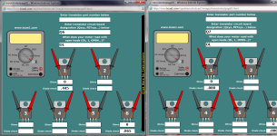
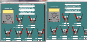
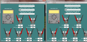
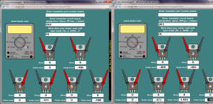
I leave the board in place and use a dental tool underneath the center leg of the transistors and while applying heat to the solder joint I gently lift that center leg up out of the board connection point. With this one center leg out of circuit you measure from that center leg to the other two legs only. This will show you which devices are really shorted, and you can pull one of the other legs of any shorted device out of the board and the short will be cleared. This will leave the bad device connected by one leg < out of circuit basically > and waiting for new parts to arrive to replace it with...hope some of this helps...
ok Q6 to Q18 tested with center legs out
ok i tested from Q6 to Q18 with center legs out of the board. here are the results thank you and i got me a new solder iron been trying it out on my other board trying to get use to how to quickly remove those transister are a pain in the butt lol but o well i'll get better haha
ok i tested from Q6 to Q18 with center legs out of the board. here are the results thank you and i got me a new solder iron been trying it out on my other board trying to get use to how to quickly remove those transister are a pain in the butt lol but o well i'll get better haha
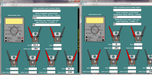
Q6 to Q18 pixs
here are the pixs forgot to post
here are the pixs forgot to post
Attachments
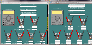
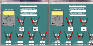
ok and i think q10 is shorted too right? and should i pull out the transister on the ones that are shorted sence i have to replace them anyways? but the third leg is the ones that are towards the rca right? and do u want me to still check transister Q7 Q7 Q8 Q9 Q10 Q12 Q16 after i pull the third legs out? or checking the other side of the amp transister?
thank you again
thank you again
Last edited:
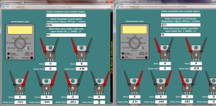
Yes its bad. Any reading below what a normal diode junction would read is bad. So anything below 340 ohms or so is bad. Usually they will read in the 20 ohms or less all the way down to 0.00 ohms. it sort of depends on the quality of you meter somewhat as to what numbers you will get. But number of 340 up to 760 are a normal junction reading.
Your amp seems to have blown all the 2N6490 outputs. Q12 is the driver for those outputs please check it carefully like you did the others it likely is also damaged with all of those outputs being bad. I have a A600 open on bench at this moment so I am comparing your info directly to my unit here
Your amp seems to have blown all the 2N6490 outputs. Q12 is the driver for those outputs please check it carefully like you did the others it likely is also damaged with all of those outputs being bad. I have a A600 open on bench at this moment so I am comparing your info directly to my unit here
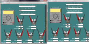
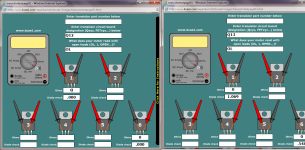
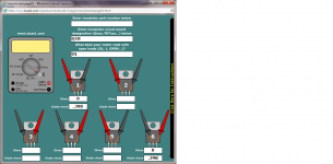
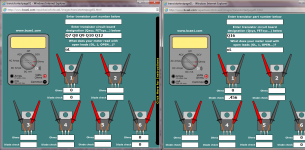
here are the reading for the otherside of the amp of transister
hey everyone here are the rest of the reading of the other side of the amp transister. The transister are still in on the otherside, so here are the results
hey everyone here are the rest of the reading of the other side of the amp transister. The transister are still in on the otherside, so here are the results
Attachments
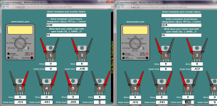
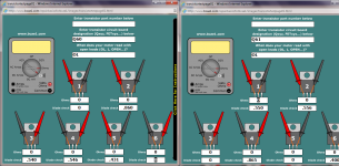
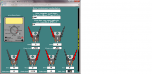
Comparing your readings to my known good amp on my bench all of these transistors are reading OK.
So I would concentrate on the other channel as your real problem for now.
Also Q54 & Q6 are not output transistors, They are lower rail pass elements < +&- 15 volt regulators >. These have large voltage drop across them when the amp is powered on so they will get hot and blow out if they are not sinked properly. This is why I work on these in the sink and why this amp must be properly clamped back into the sink before applying power to the amp for testing purposes. Make some U channel clamps like Perry recommends, please...
Ok Perry says use aluminum U channel stock material you can buy at any major hardware store. < just go into Home Depot or Lowe's and ask for tube and channel stock steel or aluminum, it comes in yard or meter lengths >
Myself I use tube steel stock with some pad material glued on the transistor side. I use tube steel stock because it does not bend or flex distort, and my clamps are tool fixtures that get used again and again. Mine are old now but they have been thru dozens and dozens of amp repairs. I also use my clamps to power test and align the amp without the bottom on the amp so mine get lots of wear and tear over the years. U channel stock will work but I chose to use tube steel stock instead.
It's your budget so you decide which material and how much you want to spend for your one or two time use of the clamps. I went overboard on mine due to the usage factors they get on my bench. PPI is the only amp made that requires these clamps. You have two amps so I would go light with aluminum, as you will likely throw them away after your done anyway....
Once you have the material you must cut it in functional lengths to accommodate the amps your working on so they cover all the power devices with there clamp pressure. And you must drill holes to allow you to use the sink screw holes to tighten them down in place clamping all the power devices against the sink with some fresh silicon heat sink compound in between the transistors and the mica insulators and the sink. Once you at this point you can test the amp with power applied and not have to worry about any heat related failures due the power devices not being pressed tightly to the sink frame.
You can replace the bad outputs once you have the above clamps made and ready to install. Once replaced you can clamp the assembly together and apply power and turn on the amps. I suggest a 3 to 5 amp fuse inline with the power just to be safe and careful not to damage anything just in case something was overlooked and or missed....
- Status
- This old topic is closed. If you want to reopen this topic, contact a moderator using the "Report Post" button.
- Home
- General Interest
- Car Audio
- PPi A600.2 #2 Powers up but with both lights on