Hi Max,
the regulator measures the voltage and adjusts the opamp to control the pass device Q1.
The accuracy of the regulator relies on the measurement.
Your circuit as posted mixes up power current flow with measurement.
Mentally extract the following components:-r2,r1,r4 & d5
now arrange them in a bridge with r2 at top left, r1 at bottom left, r4 at top right and d5 at bottom right.
the top & bottom junctions of the bridge are the sense points and the side to side junctions are where you take the comparison measurements. It is very important that the currents that flow in this bridge circuit are only the bridge measurement currents and nothing else.
Now add the opamp measuring device, inverting input to left junction
Add the two diodes as your circuit to the inverting and non inverting inputs.
Now connect c9 from non inverting input to the lower side of the r1 trace.
Connect r5 from non inverting input to the right hand junction. We have replicated your circuit exactly.
Do not add anything else to any part of this bridge measuring system. Your regulator needs this to be uncomtaminated.
Arrange all the tracks for the bridge on your circuit board so that no other component touches any of the traces. Now connect the top of the bridge to the OUTPUT connection of the regulator. Connect the bottom of the bridge to the OUTPUT Ground connection.
The two opamp supplies connect to the main current traces running to the output but NOT connected to the bridge.
I suggest you sketch the resistive bridge as a normal bridge and add d4&5, c9, r5 as described. Then draw the regulator around it . Compare your existing PCB and you will find some power currents are passing along the bridge measuring traces, disconnect them and run new power traces OR run new bridge traces, whichever is easier.
BUT do NOT share power with measurement.
maxpou said:Hi Jan,
why "wrong answer"? Maxpou
MY wrong answer; I put in some text but then realised it was BS, so I deleted it...
Jan Didden
AndrewT said:Hi Max,
the regulator measures the voltage and adjusts the opamp to control the pass device Q1.
The accuracy of the regulator relies on the measurement.
Your circuit as posted mixes up power current flow with measurement.
Mentally extract the following components:-r2,r1,r4 & d5
now arrange them in a bridge with r2 at top left, r1 at bottom left, r4 at top right and d5 at bottom right.
the top & bottom junctions of the bridge are the sense points and the side to side junctions are where you take the comparison measurements. It is very important that the currents that flow in this bridge circuit are only the bridge measurement currents and nothing else.
Now add the opamp measuring device, inverting input to left junction
Add the two diodes as your circuit to the inverting and non inverting inputs.
Now connect c9 from non inverting input to the lower side of the r1 trace.
Connect r5 from non inverting input to the right hand junction. We have replicated your circuit exactly.
Do not add anything else to any part of this bridge measuring system. Your regulator needs this to be uncomtaminated.
Arrange all the tracks for the bridge on your circuit board so that no other component touches any of the traces. Now connect the top of the bridge to the OUTPUT connection of the regulator. Connect the bottom of the bridge to the OUTPUT Ground connection.
The two opamp supplies connect to the main current traces running to the output but NOT connected to the bridge.
I suggest you sketch the resistive bridge as a normal bridge and add d4&5, c9, r5 as described. Then draw the regulator around it . Compare your existing PCB and you will find some power currents are passing along the bridge measuring traces, disconnect them and run new power traces OR run new bridge traces, whichever is easier.
BUT do NOT share power with measurement.
Andrew,
Excellent explanation, just using text and no drawings. Spot on.
Jan Didden
Hi Janneman,
you made it easy for me.
Your collaboration with Walt on the opamp regulators and the papers that followed are my source.
You make it clear.
It would be nice if a regulator Wiki pointed to the Jung website.
Btw.
I just knocked together a plug board opamp regulator based on your papers.
It uses a 317 prereg, 741 and lm4040 10V ref.
Very obviouosly not low noise and not precision. How bad will the resultant output be?
Is there an easy way to calculate the noise, line rejection etc.?
AndrewT said:Hi Janneman,
you made it easy for me.
Your collaboration with Walt on the opamp regulators and the papers that followed are my source.
You make it clear.
It would be nice if a regulator Wiki pointed to the Jung website.
Btw.
I just knocked together a plug board opamp regulator based on your papers.
It uses a 317 prereg, 741 and lm4040 10V ref.
Very obviouosly not low noise and not precision. How bad will the resultant output be?
Is there an easy way to calculate the noise, line rejection etc.?
Hi Andrew,
Thanks for your kind words.
As to the exact pro and cons, thats hard to say. The only thing you can say is that with modern opamps, carefull low noise ref and wiring / routing you can do MUCH better than with an 741. The goal in the article series was trying to do as best as possible within reasonble cost, based on measured noise, Zout, ripple etc.
The basic assumption is that audio circuits are designed *assuming* that the supply is pure, ideal DC. The closer you get, the better the final audible result.
Now obviously if you have a very sophisticated audio circuit with very high flat power supply rejection ratio, the effects of the supply will be less than with simple, straightforward follower or other relatively simple circuits which are, because of lower PSRR, much more sensitive to supply anomalies. Very general you can say, the simpler the audio circuit, the more important the supply is. The often heard remark that simple circuits need simple supplies is a common mistake, it is just the opposite!
So, the effect of the supply depends to a large extend on the circuit to be powered, not in all cases will the effect be dramatic.
Your specific question on the line rejection: this is equivalent to the PSRR of an amp. The reg can be seen as an amp with the line ripple on its supply (the raw input supply). The line rejection is basically the PSRR of the opamp.
Jan Didden
Hi Janneman,
I intend using an NE5534AN but I had a 741 to try first.
I would like to calculate the effect of substituting less well specified parts, since I have neither the equippment nor the knowledge to replicate Walt's testing procedure.
Reading your last response, the LR = opamp PSRR.
Which for the +ve supply will be the +vePSRR and for the -ve supply the -vePSRR.
AndrewT said:Hi Janneman,
[snip]Reading your last response, the LR = opamp PSRR.
Which for the +ve supply will be the +vePSRR and for the -ve supply the -vePSRR.
Tue, but in some regs (also in our super regs) the opamp is supplied from the reg output voltage itself. This gives an additional layer of isolation and in this case, the line rejection is much higher than the opamp PSRR. That may explain why this type of superreg is less critical to the opamp and you may have very good results with the NE5534 indeed.
Jan

is JRC4580 ,JRC5532, AD8620, OPA 627, OPA2134 PA suit for this psu ?
I have build this regulator with modified pcb so it can be used with dual op-amp and LM336Z 2.5v, output voltage 5V
This Regulator use with Modified USB Soundcard Phillips PSC 805.
With JRC4580 ,JRC5532, AD8620, OPA 627, OPA2134 PA my soundcard Sound OK.
I don't have osciloscope , How to know if op-amp oscillating ?
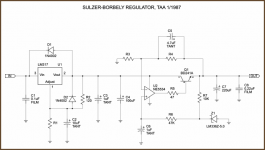
Ask to Increase sylzer bobbely regulator current
Ask to modif sylzer bobbely regulator
Hallo anyone,
i wave question about reg sylzer bobbely.
in input use lm 317 ic reg,
and output use BD241A
its mean that reg can handle 1 ampere current only?
i have question:
can i use pass transistor in LM317 , like TIUP2955/TIP3055
so the reg current can handle 3/4Amppere?
can i replace BD241A with TIP33? can handle 3Ampere current
if i cant replade BD241A with TIP33, i plan to use regulator to play CD player comp
need 2A12v and 2A 5Volt
beacuse i newbies and i need help and advice.
thx anyone
Attachments
Re: Ask to Increase sylzer bobbely regulator current
I don't believe your CD player needs these high currents.ridwans said:i plan to use regulator to play CD player comp
need 2A12v and 2A 5Volt
Re: Re: Ask to Increase sylzer bobbely regulator current
I use Asus cd 052X, for comp,
before try to connect to power amp, i use suttle external switch 5A
need help to advice, because if i made jung req it difficully to find the component in my country.
AndrewT said:I don't believe your CD player needs these high currents.
I use Asus cd 052X, for comp,
before try to connect to power amp, i use suttle external switch 5A
need help to advice, because if i made jung req it difficully to find the component in my country.
Re: Re: Re: Ask to Increase sylzer bobbely regulator current
the right spec in the CD casing is
5V 1.2A
12V 1.5V.
when 1 try to use the regulator in the schematic.
transistor BD241 and LM317 is very hot, even 1 use medium heatsink.
can you give me an option to boot current from that regulator?
thank very much
SOrry bro... i'm wrongridwans said:
I use Asus cd 052X, for comp,
before try to connect to power amp, i use suttle external switch 5A
need help to advice, because if i made jung req it difficully to find the component in my country.
the right spec in the CD casing is
5V 1.2A
12V 1.5V.
when 1 try to use the regulator in the schematic.
transistor BD241 and LM317 is very hot, even 1 use medium heatsink.
can you give me an option to boot current from that regulator?
thank very much
Attachments
- Status
- This old topic is closed. If you want to reopen this topic, contact a moderator using the "Report Post" button.
- Home
- Amplifiers
- Power Supplies
- power supply sulzer-borbely