there are two or three CL60 shown in pass PSU.
One can be for a Disconnecting Network between the Chassis connection and the Main Audio Ground connection.
One or two can be for the soft start facility.
Pass are usually shown not bypassed after start up.
If you are referring to the soft start CL60, then yes, the soft start board is a bypassable resistance that replaces the lonely CL60s.
RE: CL-60 Needed with V3 Soft Start Board?
Thanks AndrewT for the quick and thorough reply. Your help is greatly appreciated...
there are two or three CL60 shown in pass PSU.
One can be for a Disconnecting Network between the Chassis connection and the Main Audio Ground connection.
One or two can be for the soft start facility.
Pass are usually shown not bypassed after start up.
If you are referring to the soft start CL60, then yes, the soft start board is a bypassable resistance that replaces the lonely CL60s.
Thanks AndrewT for the quick and thorough reply. Your help is greatly appreciated...
Putting the top part of the RC circuit as shown into LTspice demands that there is a ground node attached to the anode of zener. Then, changing *just* C2 changes the rate at which the 1000uF cap charges up -- which operates the relay..... lower values of C2 means longer delay.....
Here is the model of the diode:
* 1N4749 24 Volt ñ5% 1W zener diode
.model D1N4749 D(Is=25.94f Rs=9.006 Ikf=0 N=1 Xti=3 Eg=1.11 Cjo=41p M=.2715
+ Vj=.75 Fc=.5 Isr=2.052n Nr=2 Bv=24 Ibv=.14951 Nbv=1.3684
+ Ibvl=164.37u Nbvl=14 Tbv1=895.83u)
I hope it is OK to simulate with that change to ground. NB. I did not bother with the LED, just the 2K2 resistor.
Attachments
To those who may use this board as an inspiration for their own custom design: allow me to suggest you consider buying a relay with a second set of contacts, i.e., a DPDT relay.
In the present design, a sloooooowly increasing ramp voltage is applied across the relay's coil. At some point, the coil voltage becomes sufficient to pull-in the armature. But the coil voltage is just barely enough and the contacts could easily hover in a meta-stable state or chatter between open and closed (as D9-D12 charge C10, while at the same time the relay coil resistance discharges C10).
The standard engineering solution for achieving an unambiguous digital (ON or OFF) output, from a slowly moving input, is hysteresis. This can be achieved by a second set of relay contacts. When the relay is not-pulled-in, the coil voltage is V(C10) minus two silicon diode drops. When the relay IS pulled-in, the coil voltage is V(C10). Presto, there are now two silicon diode drops (i.e. 1.4V) of hysteresis. The second set of relay contacts inserts, and removes, two silicon diodes from the coil circuit. Additional cost is a DPDT relay instead of an SPDT relay, two 1N4005 diodes, and a redesign of the PCB. If you wish, select a different integer instead of "two". Make it your own design!
Your recommendation re LED1 is a very good one and one well worth implementing, in my view, in the BoM. 10p each at Mouser UK.
I've updated the model. Coil resistance can be set on the schematic (without editing the library file) - just edit the .param statement for Coilres. The link above should still work.
I will think about your comments regarding a custom design. I have to admit I was hoping to be able to leverage existing product at some point
 a split was done here....http://www.diyaudio.com/forums/power-supplies/262664-soft-start-circuit-design-other-psu-issues.html
Thanks AJT. Good idea.
I have a question that's likely better posted here though. The PHE840 series caps mentioned for C2 in the BoM are listed as "not for new design". Am I right that the Kemet R46 (or R46 mini) series are suitable for this application? (Cheaper than the PHE840 as well.)
I have a question that's likely better posted here though. The PHE840 series caps mentioned for C2 in the BoM are listed as "not for new design". Am I right that the Kemet R46 (or R46 mini) series are suitable for this application? (Cheaper than the PHE840 as well.)
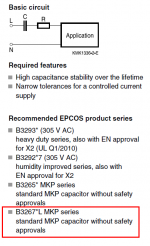
For mains voltages upto 240Vac:
Live to Neutral capacitors should be X1, or X2.
Live to Earth and Neutral to Earth capacitors should be Y1, or Y2.
X1 and Y1 are rated for upto 400Vac (between two 240Vac phases on a 3phase supply)
Some would say these are not should be and are actually MUST be, in that we have no choice.
Live to Neutral capacitors should be X1, or X2.
Live to Earth and Neutral to Earth capacitors should be Y1, or Y2.
X1 and Y1 are rated for upto 400Vac (between two 240Vac phases on a 3phase supply)
Some would say these are not should be and are actually MUST be, in that we have no choice.
who is not? readers/builders who wish to use those can do so....
there are minimum requirements, and getting over those minimum is no big deal...
the function of those series capacitors is to present an impedance to the mains
so that current is limited to what is needed to actuate the relay...
a capacitor is a capacitor, as long as you do not apply voltages
that can cause dielectric breakdowns, then you can use them...
email KEMET and ask them directly...best answer you can get...
there are minimum requirements, and getting over those minimum is no big deal...
the function of those series capacitors is to present an impedance to the mains
so that current is limited to what is needed to actuate the relay...
a capacitor is a capacitor, as long as you do not apply voltages
that can cause dielectric breakdowns, then you can use them...
Next to the PHE840 series Kemet say: "Not for New Design, please refer, only for "across-the-line" applications, to: - R46 standard version...".
email KEMET and ask them directly...best answer you can get...
Kemet's data sheet recommends reading Short Guide to Choose the Right Film Capacitor, which wasn't so easy to find with Google. I think (this pdf file) is what they're talking about. For the 1.0uF series capacitor on the soft start board, the left hand column appears to be the one that matters.
Indeed, I had asked not about 1000Vdc caps but whether a specific cap, listed by its manufacturer as a replacement for the cap listed in the BoM for a board sold by this site, was appropriate. Simple question, likely deserved of a simple response. Instead we started talking about 1000VDC caps.
Mark, thanks again. As I glance anew at the R46 series datasheet, all of a sudden "Not for use in 'series with mains' type applications' is staring back at me as if it were written in neon colour. I will look at the other series.
Particularly given this is a mains voltage project I am seeking comfort from those with experience (and, it would appear, luckily so).
I would also suggest that greater guidance/caution be given in the BoM for the store's board. As a further example, anyone using the suggested BoM for UK/European voltages and large smoothing capacitance may be interested to look at the modelled power that resistors R3-6 need to dissipate.
Last edited:
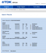
In my opinion it might be worth looking into this EPCOS film capacitor: part number B32674D6105K. Its characteristics are

This capacitor is in current production and available from distributors worldwide; see attached image from EPCOS's website. (Here is its sales page at UK Farnell)
- 1.0uF
- 350VAC
- 27.5mm lead spacing
- 19mm case height
- 5.0 amps ripple current rating @ 70C
This capacitor is in current production and available from distributors worldwide; see attached image from EPCOS's website. (Here is its sales page at UK Farnell)
Attachments
- Home
- The diyAudio Store
- Power Supply Soft Start Board (V3)