 Okay, so I finally got around to setting up the PS and amp and what do I get for it ...a 418V SHOCK! not fun...not fun at all.
 Here's the odd part, I wasn't touching the amp or, the power supply -I was touching the 3rd separate unit the volume control/ipod dock. The only wires going to and from the unit, to the amplifier, was the +R chan. Grnd +Lchan. that's it!
So I’m stumped as to why I would get the shock of my life if the unit was completely separate (or so i thought).
I'm running on three theories here:
1. B+ some how got connected to one of the signal inputs. *don't think it could be this though cause I wired those last and they were no where near B+
2. Does ceramic tile conduct electricity? Cause I setup the project in the kitchen (and no there wasn't water anywhere) always thought ceramic was an insulator.
3. Perhaps B+ was connected to ground?? (haven't checked yet but, i triple checked before hand)
I can't remember if I touched the outer case (aluminum) or, the volume pot to get the shock. Before i touched the case i was examining the amp (for smoke and what not) and I noticed that the EL84's where both lit up but the 12AX7's didn't look lit up but, of course it wasn't that dark and i don't think these are supposed to light up very bright.
Anyways...believe me when i say 'i was/am cautious" - I don't just go poking around inside circuits and this shock came from a very unusual place in my opinion.
What do you guys (or gals) think? ....find a new hobby?
") j/k
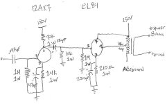
j/kThis circuit is attached.
Attachments
Using a meter check from all connections from your ac power cord to the chassis. There should be no continuity, except to ground. (What, no ground you say - add grounded power cord say I.) You have a fuse on the hot side of the ac power coming in right??
Also on an unrelated issue you need to remove the 10K resistor you show in parallel with the 1M resistor to the 6BQ5.
There are other mistakes - the spot you label AC ground should be connected to the 250V power supply output and not grounded, and the connection to the 250V supply shown on the top of the transformer is wrong as well and should be removed just leaving the plate connected to the transformer. I will also assume that you also have no ground return from the power supply chassis to the amplifier chassis which would explain the big shock. (Otherwise as drawn you would have a dead short across the supply.)
Filament connections are not shown, for 12AX7 connect one side of filament transformer to pins 4&5 and the other to pin 9 assuming 6.3V supply. 6BQ5 also connected to filament supply? Filament supply referenced to ground or better still the cathode of just one of your 6BQ5s? (Elevates filament line and reduces noise coupling from the filament to cathode.)
Coupling cap to 6BQ5 should be a small film like 0.1uF or so at 400V min.. That 0.047uF input cap is not required in most applications and can be deleted.
Do be careful! And I would say based on this experience to check that the chassis is not hot with power applied using a meter before you touch it again. Do this with meter set to AC and then DC to a good nearby ground. (Outlet ground or similar) If the supply is on a separate chassis check for differences in potential between the two chassis as well. (Same technique)
kevinkr said:Using a meter check from all connections from your ac power cord to the chassis. There should be no continuity, except to ground. (What, no ground you say - add grounded power cord say I.) You have a fuse on the hot side of the ac power coming in right??
Also on an unrelated issue you need to remove the 10K resistor you show in parallel with the 1M resistor to the 6BQ5.
There are other mistakes - the spot you label AC ground should be connected to the 250V power supply output and not grounded, and the connection to the 250V supply shown on the top of the transformer is wrong as well and should be removed just leaving the plate connected to the transformer. I will also assume that you also have no ground return from the power supply chassis to the amplifier chassis which would explain the big shock. (Otherwise as drawn you would have a dead short across the supply.)
Filament connections are not shown, for 12AX7 connect one side of filament transformer to pins 4&5 and the other to pin 9 assuming 6.3V supply. 6BQ5 also connected to filament supply? Filament supply referenced to ground or better still the cathode of just one of your 6BQ5s? (Elevates filament line and reduces noise coupling from the filament to cathode.)
Coupling cap to 6BQ5 should be a small film like 0.1uF or so at 400V min.. That 0.047uF input cap is not required in most applications and can be deleted.
Do be careful! And I would say based on this experience to check that the chassis is not hot with power applied using a meter before you touch it again. Do this with meter set to AC and then DC to a good nearby ground. (Outlet ground or similar) If the supply is on a separate chassis check for differences in potential between the two chassis as well. (Same technique)
----------
I do have a 500mA slow blow fuse.
I will check the AC to chassis for continuity of course i have three separate metal cases so i should probably check them all just to be sure.
This is not a smug "why?" but an educational "Why?"; when I ask Why should I remove the 10K resistor from circuit (because it's negligible compared to the 1M?)?
For the output trans I should make the plate ONLY go to the "Plate" label pin of the X-former and the 250V should go to the "AC Ground" label? That makes sense, my bad

Do you recommend a resistor coming from the UL tap to grid?
Now this concept of a Ground return is new to me. So basically I have to take a PSU chassis ground wire and hook it up to the chassis of the amplifier?
I thought being grounded at one point was good enough but, i guess this only applies to one whole unit (i.e. PS, amp on one chassis)
My Heater filaments are wired as such:
Grn wire from X-former to pin 4, 4, 4, 4
Grn wire from X-former to pin 5, 5, 5, 5
Parallel right? There's a ground needed?!?
I will try your other suggestions as well.
Thank you!
-Brett
Ok I’m back and this could fall into the catageory of PS still right!?!
So I added a “Ground return wire” from the ground point on the PS to the ground on the amplifier.
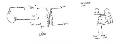
Next, I changed the wiring for the EL84’s as you see in the picture below.
Also I put my Heater wiring on there as well.
I plugged it in and measured the from the ground of the PS to the chassis of the amplifier and volume control box and both should 0V so I’m assuming that’s good as there’s no potential difference between them. However, when I attach ground to the metal chassis of the volume control or amp and connect the PS Hot leads I do get a voltage (250V). Good? Bad?
Next symptom, when I power up the amp I hear a very, very, soft buzz (from the speakers) completely acceptable, then about 10 seconds later it turns into this air plane noise or, like square waves being pushed through my speakers. The sound starts in both channels (L&R) but then fades out of the right chan. and stays in the left until I turn off the power.
Lastly, the 12AX7’s don’t appear ‘lit up’ but they feel warm to the touch..also when measuring the voltage that should be 180V for the 12AX’s it’s 250V just like what supposed to be for the EL84. So, it sounds like there’s not voltage dropping there as planned…problem?
I appreciate all the advice I’ve been given
Thanks,
-Brett
So I added a “Ground return wire” from the ground point on the PS to the ground on the amplifier.
Next, I changed the wiring for the EL84’s as you see in the picture below.
Also I put my Heater wiring on there as well.
I plugged it in and measured the from the ground of the PS to the chassis of the amplifier and volume control box and both should 0V so I’m assuming that’s good as there’s no potential difference between them. However, when I attach ground to the metal chassis of the volume control or amp and connect the PS Hot leads I do get a voltage (250V). Good? Bad?
Next symptom, when I power up the amp I hear a very, very, soft buzz (from the speakers) completely acceptable, then about 10 seconds later it turns into this air plane noise or, like square waves being pushed through my speakers. The sound starts in both channels (L&R) but then fades out of the right chan. and stays in the left until I turn off the power.
Lastly, the 12AX7’s don’t appear ‘lit up’ but they feel warm to the touch..also when measuring the voltage that should be 180V for the 12AX’s it’s 250V just like what supposed to be for the EL84. So, it sounds like there’s not voltage dropping there as planned…problem?
I appreciate all the advice I’ve been given
Thanks,
-Brett
Attachments
Finished:
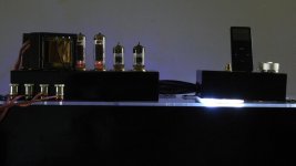
Well after all was said and done I'm finally finished.
I've attached a picutre of what it looks like and I must say it sounds pretty darn good!
The actual measured voltages ended up being 258V and 184V so the PSU II designer is accurate enough.
So, now that i'm hooked....i'll be back. I'm thinking about maybe giving it a go with the KT tubes.
Attachments
Defbrett said:This is not a smug "why?" but an educational "Why?"; when I ask Why should I remove the 10K resistor from circuit (because it's negligible compared to the 1M?)?
The 10K in parallel with 1M is essentially 10K. You want the load on the input tube to be small, say 1M. So the 10K goes. BTW 1/8W is adequate here.
Defbrett said:
Do you recommend a resistor coming from the UL tap to grid?
Typically 30 to 100R, 2W.
Defbrett said:Now this concept of a Ground return is new to me. So basically I have to take a PSU chassis ground wire and hook it up to the chassis of the amplifier?
I thought being grounded at one point was good enough but, i guess this only applies to one whole unit (i.e. PS, amp on one chassis)
There is "common" and "earth". Both are sometimes referred to a ground - sloppy practice.
Common is all the returns from positive side of your supply, through various circuit components and back to the negative side of the supply. This is then usually connected to "earth" at the same point in the chassis as the safety earth from the AC mains. All conductive elements of the chasssis should be connected to earth.
Defbrett said:My Heater filaments are wired as such:
Grn wire from X-former to pin 4, 4, 4, 4
Grn wire from X-former to pin 5, 5, 5, 5
Parallel right? There's a ground needed?!?
Your 12AX7 filaments require 12.6V across the length of the filament. If you have a 12.6V filament supply, your connection is correct. But you have a 6.3V supply, so, as Kevin said you need to connect the center of the filament (pin 9) to one end and combine pins 4/5 at the other end. That way you have 6.3V across each leg of the filament, or 12.6V total.
Parallel, yes. And yes you need a stable reference for one side of the filament supply. Preferably the Pin 9 side. You can connect it to common, or better, again as Kevin suggested, connect it to the cathode of the output tube. This will raise the reference a few volts above common and give lower noise.
Sheldon
- Status
- This old topic is closed. If you want to reopen this topic, contact a moderator using the "Report Post" button.
- Home
- Amplifiers
- Tubes / Valves
- Power Supply Design