That is not a half bad idea. I was thinking about using 120V darlingtons (I have a stash lying around waiting for a project) and using +/-50V throughout, but I think you may be on to something. If I use 240V transistors in the output stage, they can sit at +/-85V rather easily and all I would need would be an additional resistor per chip. . . .
This would also be a hell of a lot cheaper! No giant choke to buy.
Can anybody think of a reason the output transistors wouldn't like to be a different voltage than the op-amp?
This would also be a hell of a lot cheaper! No giant choke to buy.
Can anybody think of a reason the output transistors wouldn't like to be a different voltage than the op-amp?
Hi Dfdye,
normally the outputs run from the same supply as the voltage amp.
Some run the voltage amp from a separate supply from the outputs.
Some others even take some advantage from this and run the voltage amp from a slightly higher voltage than the outputs.
The disadvantage of running the outputs higher than the voltage amp is SOAR in general and the onset of second breakdown in particular.
Running the outputs at a higher than necessary voltage puts more power through them and as a consequence they run hotter. This uses up some more of your temperature derating. Further the higher voltage also limits the maximum current the devices can deliver and finally the second breakdown severely limits the available current when the output devices are asked to work above the Vce knee in the SOAR curve.
Run the outputs at no higher than the voltage amp.
There has been one exception to this. Recently a schematic was posted showing the JLH 80 Mosfet amp that had Vrails that appeared to be swapped around. To date no one has explained this anomally.
Alright, after having a few minutes to concentrate on what needs to go into this, I think I have a good design model for the choke input supply. The problem is that in order to have a high enough power handling choke, the resistance of the choke drops substantially (to about 0.3 ohms from those I have found available), making the PSU go crazy during startup. In order to make it well behaved, a resistance of 100 ohms for the choke works out quite well. Once the PSU becomes stable, the 0.3 ohm choke looks stable, but that takes several seconds according to the models I have been using. I was wondering if switching in/out a 100 ohm resistor during startup (until the power hits ~45V) using a relay would help, or would a monostable multivibrator timer setup that also cuts the outputs be a better option?
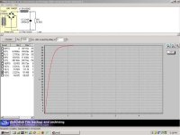
Attached is a simulation of this circuit using PSU designer II (which seems rather nice and simple for what it does). Of course it is for one rail, as I will need both a + and - rail, but I assume that both halves will behave the same way. Alternately, should I assume a 120V rail to rail and use the CT of the transformer as ground? I can always add in another cap and tie the center to ground. . . . This would eliminate one (rather expensive) choke, but I don't want to mess up the filtering if I need a choke for each rail.
Thoughts?
Thanks again!!!
Attachments
Hi,
You could try slow start.
I presume PSUD is showing oscillation of the output voltage?
Try a lower value load resistor, to achieve near your proposed quiescent current.
Now load up the PSU by inserting a range of load resistors and look at the 1second to 1.5second values.
You could try slow start.
I presume PSUD is showing oscillation of the output voltage?
Try a lower value load resistor, to achieve near your proposed quiescent current.
Now load up the PSU by inserting a range of load resistors and look at the 1second to 1.5second values.
- Status
- This old topic is closed. If you want to reopen this topic, contact a moderator using the "Report Post" button.