keypunch said:I have another balanced input circuit from a different schematic I like to take a "spin" on opinion.
John L. Males
Willowdale, Ontario
Canada
18 December 2006 23:32
Hi Key,
Take a look at this circuits...
http://sound.westhost.com/project51.htm
http://sound.westhost.com/project66.htm
http://sound.westhost.com/project87.htm
AndrewT said:it still fails both tests.
You have looked at Pass and then altered it!
Hi Andrew,
Actually Post #1241 is exactly as it is from the schematic. I have made absolutely no changes. There is a slightly different implementation in one of the other amps that I elected not to post as I was certain it would be less likely than this one to meet your approval.
The example from Post #1239 is not my design nor is it modified in anyway.
Both Post #1239 and Post #1241 are from high end companies.
Regards,
John L. Males
Willowdale, Ontario
Canada
19 December 2006 10:43
pejinm said:
Hi Key,
Take a look at this circuits...
http://sound.westhost.com/project51.htm
http://sound.westhost.com/project66.htm
http://sound.westhost.com/project87.htm
Hi pejinm,
Thanks for your posting. I have been aware of these and a few other designs for some time and in fact offered two of you suggestions in Post #549. I did not offer Project 66 as suggestion as it is for microphone input.
I was attracted to the design concept that would possibly allow one to implement an unbalanced and balanced input. I am in favour of a discrete design rather than an OpAmp design. Though if need be, I can re-implement an OpAmp design by replacing the OpAmp with some known discrete OpAmp circuits.
My first post was an attempt to implement into the quasi amp as the design looked straight forward to do so re Post #1235, but as I noted may not be correct as I assumed some aspects of the NFB and LTP interfacing. The next two examples (Post #1239 and Post #1241) were as is from the schematics of two high end designs.
I have been assuming that with an already existing LTP in an amp input circuit that I could avoid another layer in the input circuit to implement a balanced input. It seems to me this may be possible. I have not made any attempt yet to take the collective circuits and research I have done and create a design that might work as I do not have enough EE knowledge to validate my attempt. I am using my logic, rational thinking, research and cut and past to accomplish my attempts. I am very confident that Post #1235 is correct in the sense of adaptation from the circuit I modeled from and seems to be backed up once I found the example of Post #1239.
Before I posted Post #1241 I was aware of ESP Project 87 and in fact wanted to first have Andrew's feedback of Post #1241 before I posted a link to one part of Project 87 to have Andrew's thoughts on. For the moment I have not done so until Andrew has had the opportunity to decide if he wishes to comment about my Post #1244. As FYI to Andrew, my last statement does no imply you need to comment on Post #1244, just that I rather let that thought trend complete/progress before I move on.
Regards,
John L. Males
Willowdale, Ontario
Canada
19 December 2006 11:15
jacco vermeulen said:Con,
Merry Christmas.
Wishing you sweat your pants off, really downunder there
keypunch said:Hope everyone is enjoying the seasonal music on their quasi nmos amplifier.
Hi Jacco, we have had very strange weather down here. Only 18 degC when it should be around 30. So our pants stayed on.
Hi John, I wonder how many quasi's were playing. A few hundred watts of "dashing through the snow, on a one horse open....." might be hard to take though.
Merry Christmas to you.
Cheers
Q
quasi said:
Hi Jacco, we have had very strange weather down here. Only 18 degC when it should be around 30. So our pants stayed on.
The weather has been exceptionaly mild here and no snow in Toronto area yet. I think we have been about 10C above nomal so far this winter. That said we have been almost complely overcast since mid August which is very unusual and if we had more sun it clearly would have been much higher above normal for this time of year.
How about this a bit earlier in year for this area:
An October For The Record Books
November 2, 2006
The month of October will be remembered for an incredible record breaking lake effect snow storm. Thirty centimetres of snow piled up in Fort Erie on October 12th, shattering single day and monthly records for the area. The old monthly mark was a measly 4.5 cm of snow recorded in 1993. The weight of the snow knocked down trees, taking out power lines. The area was paralyzed. Parts of Western New York were hit so hard by the storm that the clean-up was still going on at month's end, almost three weeks later.
Amazingly another part of the province had over twice as much snow as Fort Erie over the month. North Bay set a new record for snow as 82 cm touched the ground in October. The old record was 38.6 cm set in 1962.
In Toronto it was rain, not snow, that kept coming all month. Over 120 mm of rain fell at Pearson Airport. That's almost twice the 63 mm monthly normal making it the fourth wettest October on record.
I ran into a man in the building here I had nto seen for few months. He was in Iran for 3 months on business as well as pleasure and some problems had to work out in family. He said it was cold in Iran and when it is warm or mild here is is cold in Iran and vice versa. It was only been this oppsite like effect in Iran over that last few years and he cites global warming as likely cause.
I suspect the weather you are having is also a result of teh sam mess that caused those disaster hurricanes in US last year and year before the four majoy hurricanes in Flordia.
Hi John, I wonder how many quasi's were playing. A few hundred watts of "dashing through the snow, on a one horse open....." might be hard to take though.
Merry Christmas to you.
Cheers
Q
Well at least here there is no snow to sing about or see. There was lots of frost this morning as I walked about 04:30 - 06:30 doing my Christmas tradition trips. Besides who said has to be a few hundred watts. How about just a few milliwatts?
Merry Christmas,
John L. Males
Willowdale (Toronto technically), Ontario
Canada
25 December 2006 19:44
Hi to all!
I have a question about DC protection. Can i use only one filter insted of two (one C22uf an one R)? I have made DC protection by quasy and it works OK, but will it bee any slower or will it in this way make any fault?
Seeing this so many happy builders makes me wanna build one pair, but not so soon i'm affraid
I have a question about DC protection. Can i use only one filter insted of two (one C22uf an one R)? I have made DC protection by quasy and it works OK, but will it bee any slower or will it in this way make any fault?
Seeing this so many happy builders makes me wanna build one pair, but not so soon
i'm affraid geminni said:Hi to all!
I have a question about DC protection. Can i use only one filter insted of two (one C22uf an one R)? I have made DC protection by quasy and it works OK, but will it bee any slower or will it in this way make any fault?
Seeing this so many happy builders makes me wanna build one pair, but not so soon
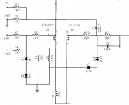
You could try leaving out the first 33k resistor and 22uF capacitor, but the circuit will trip on loud bass notes. The circuit will probably be a bit quicker in detecting DC but not so much to make a big difference. For the cost of one resistor and on capacitor my advice is to build it as is.
Most builders have found this amp fairly simple to construct although it is a large project when you consider the power supply and case construction.
The amp seems to be reliable, mine has been used most days since April 2005.
Cheers
Q
quasi said:
You could try leaving out the first 33k resistor and 22uF capacitor, but the circuit will trip on loud bass notes. The circuit will probably be a bit quicker in detecting DC but not so much to make a big difference. For the cost of one resistor and on capacitor my advice is to build it as is.
Q
Well, the thing is that i have build it and forgot to add second resistor and capacitor, i had i mind "that type" of schematic
Another question: I have tested protection by aplying 12 volts (+ and -) and measured very small voltage after the input resistor which was much lower then 1/3 like you said. For that i put 2 caps, connected in series, electrolitic type that have 25 volts each. Would that be enoguh or they have to be at least 35 volts each?
Hi Geminni,`
Oops I made an error. The voltages I posted would be correct if Q1 wasn't there. You are of course measuring the base - emitter voltage which will be about 0.6v.
Whether the voltage of your capacitors will be enough depends on what rails you are using. Can you let me know and attach a drawing of input circuit.
Cheers
Q
recomendatin for design
i'm going to recommend the addition of a couple of components to the output stage. not really neccesary with mosfets, but will definitely improve the reliability when using bipolars. (2) 1n4007 diodes, the first connected from the amp side of the output choke to the +60v rail, cathode to the +rail. the other from the amp side of the output choke to the -60v rail, cathode to the choke. this will damp any back emf from the speakers (improves damping factor, too) and keep them from reverse biasing output devices (important with bipolar outputs, but mosfets have internal diodes already).
also, a DC servo which gives a separate DC feedback path, and eliminates the need to "tweak" the diff amp. i'll test it first and post the results and schematic.
i haven't really seen much about this next one in this thread, so i'll just put this one out there for discussion..... select your mosfets for the lowest RDSon possible, it will reduce distortion and increase output efficiency and available output current.
dc prot caps
as long as you have that 33k resistor there before the cap. i don't think the cap voltage is critical. i would, however tell you that according to general reliability principles, i would use either a 50v nonpolarized cap there, or two 50v caps in series with the neg sides tied together, just so you don't smoke the cap if an output device shorts, or an input transistor fails and latches the output to a rail.
as long as you have that 33k resistor there before the cap. i don't think the cap voltage is critical. i would, however tell you that according to general reliability principles, i would use either a 50v nonpolarized cap there, or two 50v caps in series with the neg sides tied together, just so you don't smoke the cap if an output device shorts, or an input transistor fails and latches the output to a rail.
Re: dc prot caps
unclejed,
I am curious as general approach to make a bipolar from two electrolytics should the negative sides of the caps be tied together? I ask to understand. So far I have see either the negative or positive sides tied together. I have not discovered if is circuit application specific, does not matter, or if some designers are not as well informed as they ought to be.
Regards,
John L. Males
Willowdale, Ontario
Canada
29 December 2006 04:03
unclejed613 said:... i would use either a 50v nonpolarized cap there, or two 50v caps in series with the neg sides tied together, ...
unclejed,
I am curious as general approach to make a bipolar from two electrolytics should the negative sides of the caps be tied together? I ask to understand. So far I have see either the negative or positive sides tied together. I have not discovered if is circuit application specific, does not matter, or if some designers are not as well informed as they ought to be.
Regards,
John L. Males
Willowdale, Ontario
Canada
29 December 2006 04:03
Hi Key,
back to back polarised caps can be either -Ve to -Ve or +Ve to +Ve.
the effect and protection is the same.
For least distortion of the signal, the common point between the caps should be biased with a DC voltage exceeding the peak signal (AC) voltage but less than the DC rating of the caps.
Unc,
imagine, for a moment, the senario of the output slewing to one supply rail. What voltage will appear across the capacitor? The supply rail voltage!!!!!!! and it could be either supply rail.
It would be better to use a film cap or a non polarised high voltage electrolytic.
- Home
- Amplifiers
- Solid State
- Power amp under development