No..................or (with the simplification P = U² / R; 75 V could feed about > 1400 W RMS into a 4 Ohm load --- ...............
Measure your chipamp.
Maximum Power is Vpk * Ipk / 2 into your load.
For a +-75Vdc PSU expect a normal maximum Voltage into your 8r0 load of ~65Vpk.
This gives a maximum power of 65^2 / 8 / 2 = 264W into 8ohms speaker or 528W into 4ohms speaker.
If you optimise the amplifier to deliver high current you may get as much as 600W into 4r0 (~69Vpk).
But equally, if you don't optimise the amplifier to deliver current you could get only 400W into 4r0 (~56Vpk).
As I said, go and measure you chipamp, into 32r, 16r0, 8r0 and 6r0 to see what happens when you ask the chipamp to deliver higher current.
Last edited:
Hello, AndrewT!
Thanks for your reply. Ahh... my oversimplification seems to be really far away from reality. And now I understand better, why you recommended me to work with smaller things, e.g. a chipamp, before trying to build a real "poweramp" --- i think you ment to teach me some fundamental rules of such circuitry, by doing this. Unfortunately that chipamp doesn´t belong to me any more, cause now it is an active module in a little subwoofer of a former workmate.
But that´s not the main point of interest, I think... Hm. With optimization for high current probably you mean high value of filter capacitors, maybe about 80mF or more per rail. That wouldn´t be impossible, I can get them on relatively low price. Butif the +/- 75 (65) V maximum would be ca. 600 Watts, then I´d have to go for much higher rail voltage. Maybe +/- 100 V (under load +/- 90V).
Couldn´t one feed the output stage with higher voltage than the driving stage?
I saw some diagrams of commercial AB-amps, where that was the case. But probably this would not be that easy. Is there a any kind of feedback through the rail lines? Only one thing would be easy: I got many, many smaller transformers, which would be able to do the job. But what are the other complications with such a solution?
I think, the FETs would need higher bias current, to work with similar linearity/THD. But how much? I fear, the overall bias current has to grow like the possible max. output power. And would this be the only problem? (Except the obvious ones: Bigger voltage rating of min. 120 V for C9 - C13 (before: 100 V); value changing of C11 and c13 to ca. 1000µF or more, and C12 to 0.1µF; reducing R35 to 4.7 Ohms or so)
Surely not, I suppose. I expect I´d have to find right values for gate resistors (doesn´t higher rail voltage require higher current for the gate?), maybe for source resistors, too (my "special" 450´s have slightly higher on-resistance, like "normal", but eventually not enough, so 0.4 Ohms would be better?).
Oh my god. So many things, I´m unable to calculate, only can estimate.
Another thing: What would the sign mean, that looks like a fork with 3 prongs? That every sign has to be connected with a own resistor with the value of R2?
Please, guys, answer me some of my questions. I got many, many FETs, but every one which blows to heaven would make me sad...
Yours,
Freddy
Hello, AndrewT!
Thanks for your reply. Ahh... my oversimplification seems to be really far away from reality. And now I understand better, why you recommended me to work with smaller things, e.g. a chipamp, before trying to build a real "poweramp" --- i think you ment to teach me some fundamental rules of such circuitry, by doing this. Unfortunately that chipamp doesn´t belong to me any more, cause now it is an active module in a little subwoofer of a former workmate.
But that´s not the main point of interest, I think... Hm. With optimization for high current probably you mean high value of filter capacitors, maybe about 80mF or more per rail. That wouldn´t be impossible, I can get them on relatively low price. Butif the +/- 75 (65) V maximum would be ca. 600 Watts, then I´d have to go for much higher rail voltage. Maybe +/- 100 V (under load +/- 90V).
Couldn´t one feed the output stage with higher voltage than the driving stage?
I saw some diagrams of commercial AB-amps, where that was the case. But probably this would not be that easy. Is there a any kind of feedback through the rail lines? Only one thing would be easy: I got many, many smaller transformers, which would be able to do the job. But what are the other complications with such a solution?
I think, the FETs would need higher bias current, to work with similar linearity/THD. But how much? I fear, the overall bias current has to grow like the possible max. output power. And would this be the only problem? (Except the obvious ones: Bigger voltage rating of min. 120 V for C9 - C13 (before: 100 V); value changing of C11 and c13 to ca. 1000µF or more, and C12 to 0.1µF; reducing R35 to 4.7 Ohms or so)
Surely not, I suppose. I expect I´d have to find right values for gate resistors (doesn´t higher rail voltage require higher current for the gate?), maybe for source resistors, too (my "special" 450´s have slightly higher on-resistance, like "normal", but eventually not enough, so 0.4 Ohms would be better?).
Oh my god. So many things, I´m unable to calculate, only can estimate.
Another thing: What would the sign mean, that looks like a fork with 3 prongs? That every sign has to be connected with a own resistor with the value of R2?
Please, guys, answer me some of my questions. I got many, many FETs, but every one which blows to heaven would make me sad...
Yours,
Freddy
I write in German
Lohnt sich die Arbeit nicht,
gehe zu Class D ucd 1200W using 2 mosfets,
ist auch Quasi Amp design
dann kansst Class AB Quasi vergessen
Hello, Maroof!
Sorry for late reply, yesterday got into bed early, and now I was coming home right now. So...
I think you can use it, although you can´t by far expect the two channels to deliver continuous 350 Watts (but therefore, real continuous [what music programme material, what is really transient in nature, normally would never! need] power of 2x350W, one could suggest nearly 3000 VA). But one of my "teachers" (I´m a beginner, so I can only repeat what more experienced people say... ) says, the absolute minimum would be a VA rating equal to needed power in Watts.
You got a little more, so it exceeds this absolute minimum. Sorry for this "unclear" statement, but what exactly you can expect would also be dependent on your load impedance and also on filter cap value (and a little dependent also on the caps´ ESR). I really hope that another one, which knows more, will intervene now, cause, I only can repeat, I`m a beginner.
Good luck!
Yours,
Freddy
Sorry for late reply, yesterday got into bed early, and now I was coming home right now. So...
I think you can use it, although you can´t by far expect the two channels to deliver continuous 350 Watts (but therefore, real continuous [what music programme material, what is really transient in nature, normally would never! need
] power of 2x350W, one could suggest nearly 3000 VA). But one of my "teachers" (I´m a beginner, so I can only repeat what more experienced people say... ) says, the absolute minimum would be a VA rating equal to needed power in Watts.You got a little more, so it exceeds this absolute minimum. Sorry for this "unclear" statement, but what exactly you can expect would also be dependent on your load impedance and also on filter cap value (and a little dependent also on the caps´ ESR). I really hope that another one, which knows more, will intervene now, cause, I only can repeat, I`m a beginner.
Good luck!
Yours,
Freddy
2SC1845
I can not find 2SC1845 in Viet Nam. So, pls adv me the another one to replace 2SC1845
tks 4 ur help
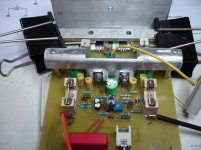
John, here's a pic of my 2SC1845's. Do yours look like this?
Cheers
I can not find 2SC1845 in Viet Nam. So, pls adv me the another one to replace 2SC1845
tks 4 ur help
Direct replace 2SC1845 (pin to pin) is 2SC2240.
Somewhere in Nhat Tao electronics market sell them. But, i wonder they're from what manufacturers? Toshiba has discontinued long time ago.
Or 2N5551, but, they're lower gain.
BC546B/C. If you get lower rail. Their Vce is only 65V.
Or cascoded, with a small signal devices like BC550C, JFET or 2SC1815 (very many in this market).
//We're countryman.
nmos200
Hi to all.
here you can see my nmos200 .QUASI'S NMOS200 - YouTube
and here you can listen it.NMOS 200 IRF540 - YouTube
Hi to all.
here you can see my nmos200 .QUASI'S NMOS200 - YouTube
and here you can listen it.NMOS 200 IRF540 - YouTube
Attachments
How to find ampe of module?
TomWaits said:
I like the LED to show state. I am hoping I can modify quasi's DC detect to have LED for Normal and DC detect states.
Shawn, I know the toroids you mentioned. How many did you pick up? They actually came in 40, 43.5 and 44V versions all with the a 12V secondary as well. The 44V versions came in either 926VA or 1127VA versions. I have one 40-0-40, a 43.5-0-43.5 and 44 with 2 of the 44-0-44's being 1127VA versions, for a total of 6 that I have. Very heavy as I am sure you are aware and they have no more in the warehouse.
The made in China 38v and 44V ones they have now are poor quality and no bonus 12V secondary.
I also picked up about year ago ILP toroids, now Piltron from Active. I picked up two 15-0-15 225VA, two 25-0-25 225VA and a 20-0-20 225VA. The 15V ones have 4 seperate secondaries of 15V each. The others have seperate secondaries, not centre tapped, each were $10.00 each. The 15V I hope will be good for tweeter amps. The others good for low power amps.
I assume the 44-0-44 ones you have are to build quasi's amp? Are your 44-0-44 926VA or 1127VA ones?
Regards,
John L. Males
Willowdale, Ontario
Canada
22 May 2006 03:22
I'm building NMOS350 amplifier, 6 FET and I hv some question.
1. How to calculate the ampe which need to supply to amplifier?
2. "44v-0-44v 926VA" Do mean: 926VA/88v = 10.5A?
3. If I use 20A of toriod, is ok for amplifier?
Don't worry about current from the transformer.
Use the VA rating to determine it's suitability.
The amplifier draws it's current from the smoothing capacitors not the transformer.
The transformer just re-charges the smoothing capacitors as the voltage drops.
926VA is good for amplifier maximum power from 926W to 463W
Use the VA rating to determine it's suitability.
The amplifier draws it's current from the smoothing capacitors not the transformer.
The transformer just re-charges the smoothing capacitors as the voltage drops.
926VA is good for amplifier maximum power from 926W to 463W
anyone still have a Quasi amp running ? Happy with it ?
Yep, the bipolar version : Brother of quasi. He deliver daily fine muisic to my hear....
Marc
Tks Walkalone for ur hepl.
I hv finished my Nmos350 amp and got problem in test.
As Quasi's Guide, I replaced the fuse with 100 ohm/5w & 10ohm/3w resistor then adjusted VR2 to get 9v & 0.9v.
But when I insert the fuse in PCB and power up the amp, about 2 minutes later R19, R22 and some 0.33R get fire.
I can't understand what's wrong????
My toroid is 52v 0 52v, out diameter: 18.5cm, hight: 8.5cm, weight: 11kg, secondary wire dia: 2.2mm. Is it ok for NMOS350 amp???
Tks Walkalone for ur hepl.
I hv finished my Nmos350 amp and got problem in test.
As Quasi's Guide, I replaced the fuse with 100 ohm/5w & 10ohm/3w resistor then adjusted VR2 to get 9v & 0.9v.
But when I insert the fuse in PCB and power up the amp, about 2 minutes later R19, R22 and some 0.33R get fire.
I can't understand what's wrong????
My toroid is 52v 0 52v, out diameter: 18.5cm, hight: 8.5cm, weight: 11kg, secondary wire dia: 2.2mm. Is it ok for NMOS350 amp???
Have you check all component orientation as diode and electrolytics?
Marc
Hallo all,
I have also got a problem with the nmos350. I have adjusted offset to 2mv, bias to 900mv tested over the 10 ohm resistors. That is on the positive rail, the bias on the negative rail is about 47mv less, should this be a problem ? I had a bulb current limiter in as well. I inserted the fuses and put on some music, it played but was very sharp. Then I removed the bulb, inserted the 10ohm resistors and re adjust the offset and bias. Put back the fuses and after a couple of minutes R22(220ohm) started smoking. Any ideas what could be the problem. I am running on 62V rails.
I have also got a problem with the nmos350. I have adjusted offset to 2mv, bias to 900mv tested over the 10 ohm resistors. That is on the positive rail, the bias on the negative rail is about 47mv less, should this be a problem ? I had a bulb current limiter in as well. I inserted the fuses and put on some music, it played but was very sharp. Then I removed the bulb, inserted the 10ohm resistors and re adjust the offset and bias. Put back the fuses and after a couple of minutes R22(220ohm) started smoking. Any ideas what could be the problem. I am running on 62V rails.
- Home
- Amplifiers
- Solid State
- Power amp under development