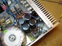
Note holes drilled in the bottom panel to help cool the small heatsink (fan ventilated case). As you all know this little heatsink gets very warm (hot?).
Amp is in service fed by the pre-amp section of a cambridge integrated amplifier. Sounds Amazing!
Cheers
Quasi
Amp is in service fed by the pre-amp section of a cambridge integrated amplifier. Sounds Amazing!
Cheers
Quasi
Attachments
Heatsink Envy
Hi Taj
About 6 years ago a company I worked for wrote off of a high capacity UPS. It was as big as a large fridge and almost completely surrounded by heatsinks each measuring 300mm long by 450mm high.
I made an offer to remove it from site at no cost to them, and they acccepted. Apart from the heatsinks I also got a huge wiring loom, about 60 IRFP450's, and stacks of other components.
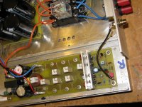
I cut the heatsinks to the height I need on my friends mill and with a some thick sheet aluminium I have a case.
The down side is that my cases can only be about 300mm deep (internally) and there is the odd drill hole that I have to watch out for, but the upside is that I have stacks of the stuff ready to be cut.
Cheers
Q
Hi Taj
About 6 years ago a company I worked for wrote off of a high capacity UPS. It was as big as a large fridge and almost completely surrounded by heatsinks each measuring 300mm long by 450mm high.
I made an offer to remove it from site at no cost to them, and they acccepted. Apart from the heatsinks I also got a huge wiring loom, about 60 IRFP450's, and stacks of other components.
I cut the heatsinks to the height I need on my friends mill and with a some thick sheet aluminium I have a case.
The down side is that my cases can only be about 300mm deep (internally) and there is the odd drill hole that I have to watch out for, but the upside is that I have stacks of the stuff ready to be cut.
Cheers
Q
I have read all 2864 posts and this is the amp for me.Good work!! I am running a ampslab C200 for sub use and was going to build the c300 (which is very similar to the Quasi amp..current mirror,similar VAS and LTP topography)when saw the Quasi.
I have already laid out a modified version of the PC with 4 IRFP450 outputs,drivers on main HS and hefty VAS HS. After reading about some of the proposed mods to the circuit, I will
use a red LED for the constant current source and fuse the whole
amp.
The final version will be a hybrid of the NMOS200 and 350
powered by a 800VA 45-0-45 toroid w/20000uf per rail.(should get 150w/8 and 250w/4... no 2 .
.
It took a long time
6 hours to lay out the board(I use graph paper
,punch, rub on donuts ,then hand paint the pattern on before etching) ...see last ampslab C200 post for example. primitive,but can match photo method.
BTW..Quasi ,do you use(abuse)your amp.. parties ,speaker testing,hot rooms,loud Rock music,etc. And is your original still working?
I have already laid out a modified version of the PC with 4 IRFP450 outputs,drivers on main HS and hefty VAS HS. After reading about some of the proposed mods to the circuit, I will
use a red LED for the constant current source and fuse the whole
amp.
The final version will be a hybrid of the NMOS200 and 350
powered by a 800VA 45-0-45 toroid w/20000uf per rail.(should get 150w/8 and 250w/4... no 2
.It took a long time
6 hours to lay out the board(I use graph paper
,punch, rub on donuts ,then hand paint the pattern on before etching) ...see last ampslab C200 post for example. primitive,but can match photo method.
BTW..Quasi ,do you use(abuse)your amp.. parties ,speaker testing,hot rooms,loud Rock music,etc. And is your original still working?
Hi Quasi,
I chanced upon this thread while looking for a 200 watt amplifier design. I have some questions which probably have been asked before and answered but tracking it in down in 115 pages of thread will be tedious.
1. You use quasi-complimentary output transistors. This is not commonly done. What is the reason you decided on this topology instead of true complimentary?
2. Is it possible to modify your design to use true complimentary output transistors?
Thanks.
taj said:Does that resistor inside the coil affect the coil's value much?
..Todd
Sorry Todd, forgot this bit.
The resistor inside the coil should not make much difference at all. In any case the final value of the inductance of the coil is not that important. I only use it to prevent RF picked up by the speaker leads from entering the amp. At audio frequencies the coil has negligible effect.
Just in case the temptation for some readers is too great, I will not be drawn into a coil v sonics discussion. There is another seamingly endless thread on this topic elsewhere in DIYA land.
Cheers
Quasi
Hi Ostripper,
Glad you like the concept of the Nmos series and good luck with your project. If you use a red LED you will need to re-calculate the resistor values for the two constant current source transistors. Basically the current will be the forward voltage of the LED minus 0.6v divided by the resistor value.
My own build has been in service since March 2005 without any problem at all. It has spent most of it's time at a friends house driving a pair of IMF speakers on a daily basis.
It has also been used at a few parties driving a pair of PA speakers at around maximum power for extended periods, again without any problems at all.
The power supply you have in mind sounds about right.
Cheers & good luck.
Quasi
caesar148 said:Hi Quasi,
I chanced upon this thread while looking for a 200 watt amplifier design. I have some questions which probably have been asked before and answered but tracking it in down in 115 pages of thread will be tedious.
1. You use quasi-complimentary output transistors. This is not commonly done. What is the reason you decided on this topology instead of true complimentary?
2. Is it possible to modify your design to use true complimentary output transistors?
Thanks.
Yes it's become quite a long thread.
The reason I chose a quasi-complementary design was to use up some of the N-Channel FETs I had collected over the years. With some tweaking and with input from other DIYA members I was able to achieve what seems to be a pretty good design.
It is easy to convert this amp to a true complementary design, but there are lots of these designs out there and then it wouldn't be a Quasi. One of the challenges would be finding well matched P-channel devices.
One of the benefits of the all N-channel design is the availability of very robust and cheap output FETs.
Cheers
Q
quasi said:
The reason I chose a quasi-complementary design was to use up some of the N-Channel FETs I had collected over the years.
---
One of the benefits of the all N-channel design is the availability of very robust and cheap output FETs.
Cheers, Q
Good way to go, quasi

N-channel amplifiers.
Use devices that can be even more more complementary
than so called complementary NPN PNP transistors
I have never seen, yet, a true complementary npn + pnp.
No matter if is go for Bipolar or MOSFET technology ....
Maybe in some future .. we get some very good complementary Power Devices ???
the hookup of designing quasi n-channel amplifiers
is of course
you have to, at some stage, use npn + pnp not so complementary drivers
no matter how you turn yourself .. you will always have a backside
Quasi , thanks for the tip on the led . I breadboarded this amp
today and it works (even with 25-0-25 junkbox Xformer-34-0-34vdc...very clear highs!!)had to reduce R7 to 6K8,but it works.
For your 2 diodes(D1/2) you get 1.4 to 1.5v drop. A red led has 1.6 - 1.7v drop.Did you mean to recalculate R11 or R8/15??
I replaced R11 with a 10k trimmer and 18k resistor to feed the led and was able to get a variable current source (1.5 to 1.7v).
also added a cap(.1uf) across the LED for stability(same as
ampslab c200/300).Measured T4 gets 2-5ma depending on trimmer.
The best mod I really want to do is a outboard opto-isolator
based adjustable threshhold overcurrent sensor to really make this (and my other amps) truely "bulletproof".
This circuit wound monitor for excessive current across emitter resistors then use an adjustable RC time constant after the isolator fed to a 3 input OR gate + flipflop with countdown timer (4017).
I,ve alredy built this circuit for turn on delay use but with this
advancement it would detect overcurrent,DC at output (that would create overcurrent) and when you first turn the amp on
the countdown would start, 10seconds later the flip would flop

") and viola -soft start.
and viola -soft start.
I will post this circuit soon as a gift back to the thread.
time for tinkerin' bye..
today and it works (even with 25-0-25 junkbox Xformer-34-0-34vdc...very clear highs!!)had to reduce R7 to 6K8,but it works.
For your 2 diodes(D1/2) you get 1.4 to 1.5v drop. A red led has 1.6 - 1.7v drop.Did you mean to recalculate R11 or R8/15??
I replaced R11 with a 10k trimmer and 18k resistor to feed the led and was able to get a variable current source (1.5 to 1.7v).
also added a cap(.1uf) across the LED for stability(same as
ampslab c200/300).Measured T4 gets 2-5ma depending on trimmer.
The best mod I really want to do is a outboard opto-isolator
based adjustable threshhold overcurrent sensor to really make this (and my other amps) truely "bulletproof".
This circuit wound monitor for excessive current across emitter resistors then use an adjustable RC time constant after the isolator fed to a 3 input OR gate + flipflop with countdown timer (4017).
I,ve alredy built this circuit for turn on delay use but with this
advancement it would detect overcurrent,DC at output (that would create overcurrent) and when you first turn the amp on
the countdown would start, 10seconds later the flip would flop
and viola -soft start.I will post this circuit soon as a gift back to the thread.
time for tinkerin' bye..
good.ostripper said:
This circuit wound monitor for excessive current across emitter resistors then use an adjustable RC time constant after the isolator fed to a 3 input OR gate + flipflop with countdown timer (4017).
I,ve alredy built this circuit for turn on delay use but with this
advancement it would detect overcurrent,DC at output (that would create overcurrent) and when you first turn the amp on
the countdown would start, 10seconds later the flip would flop
I will post this circuit soon as a gift back to the thread.
I'll wait.
crackpot idea.Edey said:Hi
I have built bridge amplifier based on Quasi's Nmos200. Totally used 8xIRFP260N.
It works at +-50V rail voltage, so 100V into 4 ohm load.
Current was about 6-7A at music signal.
Works very good!!! I'm very happy with it.
+-50V with 2pair into a 2ohm reactive load.
An accident waiting to happen.
Why so?
It already worked for one day at almost 3/4 power (I completed it yesterday).
Subwoofer, that i used (Ground Zero GZTW 38T was overloaded by this amplifier. I don't think that it would be an accident.
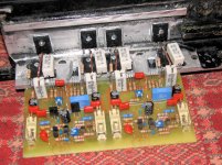
Here is photo in assebly stage with no T6, T7 transistors installed
Note: I used NE5532 op-am (precisely 3 op-amps):
First as non-inverting op amp to amplify signal
Second as low-pass active filter
Third as phase invertor
It already worked for one day at almost 3/4 power (I completed it yesterday).
Subwoofer, that i used (Ground Zero GZTW 38T was overloaded by this amplifier. I don't think that it would be an accident.
Here is photo in assebly stage with no T6, T7 transistors installed
Note: I used NE5532 op-am (precisely 3 op-amps):
First as non-inverting op amp to amplify signal
Second as low-pass active filter
Third as phase invertor
Attachments
Im working on Nmos500W amp almost finished just waiting to fire up. I need your help to adjust Bias. I think amplifier settings depend on different technique. To set VR1 and VR2.Multimeter I own Fluke 80 Series, I need some clarification, how to adjust Bias current. Can someone please put in detail the procedure? Selection of Multimeter range? How to place multimeter Red probe and Black probe on the circuit point while setting Bias current.
Thanks
Thanks
Bushulo said:Im working on Nmos500W amp almost finished just waiting to fire up.
I need your help to adjust Bias.
I think amplifier settings depend on different technique.
To set VR1 and VR2.Multimeter I own Fluke 80 Series, I need some clarification, how to adjust Bias current.
Can someone please put in detail the procedure?
Selection of Multimeter range?
How to place multimeter Red probe and Black probe on the circuit point while setting Bias current.
Thanks
Hello.
You can find these details in Construction guide PDF for NnMOS350/500
http://www.adam.com.au/cgpap/QuasiWeb/nmos350_500.htm
Basically you replace fuses with 100 Ohm resistors.
And measure voltage across.
From the PDF:
3. Remove the PCB fuses and replace with 100 ohm 5 watt resistors. Connect a multimeter
that is set to the 20 volt scale across the positive rail 100 ohm resistor.
4. Check that the power supply connections are correct one last time and switch on. If the
multimeter reading goes off-scale, turn off immediately and find the problem. Check also the
100 ohm 5 watt resistors; they may have gone open cct.
5. If everything seems ok adjust VR2 to set the output stage bias current, by measuring the
voltage across the positive rail resistor. Adjust for a reading of 3 volts per output FET pair. I.e.
For a 6 FET board set for a voltage of 9 volts. This equates to a bias current of 30mA per
FET pair or 90 mA total. For a 10 FET board set for a voltage of 15 volts.
hi quasi
without your permission i modified your nmos200 pcb to suit my needs
i will be using this pcb for nmos350 please comment on this pcb
and also please suggest a matchiing pre amplifier based on opamps
i have already made nmos200
thanks for the lovely amp
with best regards
without your permission i modified your nmos200 pcb to suit my needs
i will be using this pcb for nmos350 please comment on this pcb
and also please suggest a matchiing pre amplifier based on opamps
i have already made nmos200
thanks for the lovely amp
with best regards
Attachments
- Home
- Amplifiers
- Solid State
- Power amp under development