Inductor
Re: inductor Post #970
quote:
Originally posted by davorinjo
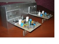
Hello, I was wandering, Quasi how would I wind the 4 uH Inductor. What size wire should I use and how many turns on which diameter should I wind?
I just wind about 30 turns of 1mm enamelled wire around an air core about 1cm in diameter and 1 cm high. You will end up with about 3 layers. Try to find a plastic bobbin like the one in my pics to make it easier. But don't stress if you can't, have a look at what Shawn did. It looks like he wound some around a 5 watt resistor.
Re: inductor Post #970
quote:
Originally posted by davorinjo
Hello, I was wandering, Quasi how would I wind the 4 uH Inductor. What size wire should I use and how many turns on which diameter should I wind?
I just wind about 30 turns of 1mm enamelled wire around an air core about 1cm in diameter and 1 cm high. You will end up with about 3 layers. Try to find a plastic bobbin like the one in my pics to make it easier. But don't stress if you can't, have a look at what Shawn did. It looks like he wound some around a 5 watt resistor.
Originally posted by superseadragon I guess I should skim through the past posts before asking questions!!
This could be the easiest method? You could use "some kind" of tape if you do not have heat-shrink & gun. No bobbin required though a plastic bobbin shouldn't be hard to find.
Blessings,
Tex
Transformer
I was advised to derate my power for the Nmos350 as a bass amplifier for continuous power reasons. I am looking at a 45+45 500VA transformer. It is a bit of overkill I think but I am having trouble finding anything less than 500VA. Now at this voltage (+/-63V rails) quasi's web page suggests using only 4 FETs on the output. Would the fact that I am using this for a bass application require me to use more FETs, or do you all think that the IRFP450 can take it and I can go for only 4?
I was advised to derate my power for the Nmos350 as a bass amplifier for continuous power reasons. I am looking at a 45+45 500VA transformer. It is a bit of overkill I think but I am having trouble finding anything less than 500VA. Now at this voltage (+/-63V rails) quasi's web page suggests using only 4 FETs on the output. Would the fact that I am using this for a bass application require me to use more FETs, or do you all think that the IRFP450 can take it and I can go for only 4?
Re: Transformer
I've tested the NMOS350 with +/- 60V rails and 4 FETs. They do get hot, but I think that can be countered by using heavy heat sinks. Also go easy on the bias current. At 30ma per pair, the FETs blow very quickly when overdriven. Start at around 10-15 ma per pair first and see how it goes.
Hari
superseadragon said:I was advised to derate my power for the Nmos350 as a bass amplifier for continuous power reasons. I am looking at a 45+45 500VA transformer. It is a bit of overkill I think but I am having trouble finding anything less than 500VA. Now at this voltage (+/-63V rails) quasi's web page suggests using only 4 FETs on the output. Would the fact that I am using this for a bass application require me to use more FETs, or do you all think that the IRFP450 can take it and I can go for only 4?
I've tested the NMOS350 with +/- 60V rails and 4 FETs. They do get hot, but I think that can be countered by using heavy heat sinks. Also go easy on the bias current. At 30ma per pair, the FETs blow very quickly when overdriven. Start at around 10-15 ma per pair first and see how it goes.
Hari
Re: Re: Transformer
The power matrix on the web site is for domestic use only and recommends 4 FETs into 8 ohms for 65 volt rails. For 4 ohms you must use 6 FETs. For a bass guitar amp running 63 volt rails into 4 ohms I recommend 8 FETs.
If the FETs are blowing with 30mA per pair then something is wrong. The idle current should not have a bearing on how hard you can actually drive the amp, unless as you say the heatsink is too small and already hot from the power dissipation at idle.
Cheers
Q
superseadragon said:I was advised to derate my power for the Nmos350 as a bass amplifier for continuous power reasons. I am looking at a 45+45 500VA transformer. It is a bit of overkill I think but I am having trouble finding anything less than 500VA. Now at this voltage (+/-63V rails) quasi's web page suggests using only 4 FETs on the output. Would the fact that I am using this for a bass application require me to use more FETs, or do you all think that the IRFP450 can take it and I can go for only 4?
The power matrix on the web site is for domestic use only and recommends 4 FETs into 8 ohms for 65 volt rails. For 4 ohms you must use 6 FETs. For a bass guitar amp running 63 volt rails into 4 ohms I recommend 8 FETs.
jethari said:
I've tested the NMOS350 with +/- 60V rails and 4 FETs. They do get hot, but I think that can be countered by using heavy heat sinks. Also go easy on the bias current. At 30ma per pair, the FETs blow very quickly when overdriven. Start at around 10-15 ma per pair first and see how it goes.
Hari
If the FETs are blowing with 30mA per pair then something is wrong. The idle current should not have a bearing on how hard you can actually drive the amp, unless as you say the heatsink is too small and already hot from the power dissipation at idle.
Cheers
Q
Re: Biasing of the Nmos350
You amp will work great at 63v. VR2 will allow you to set the bias correctly. If it does not have enough "reach" you could increase the value of R13 to 560R.
Cheers
Q
superseadragon said:If I derate the power supply, isn't that going to throw all the biasing off? or will the pots allow me to "rebias" the transistors? My concern is mostly towards the voltage gain stage and the MJE3xx transistors driving the FETs.
You amp will work great at 63v. VR2 will allow you to set the bias correctly. If it does not have enough "reach" you could increase the value of R13 to 560R.
Cheers
Q
PCB
I am right now tracing out my pcb. Yet, I have found a difference between the pcb and the schematic. T8, on the pcb, has a 01u cap across the collector and emitter. In the schematic, it doesn't appear. Am I overlooking something? Also, the 10R resistor connects the ground the the chasis correct?
Thanks in advance.
Usually a good amplifier can run on a wide range of voltages without too much difference in operation. CCS VAS is better for that, but even VAS resistor amps are fine also for running lower voltages. Adjust the bias most of the time is all that's needed.
*A common thing I've found at DIY audio is people using 2 9V batteries in series to get split 18V (+/-9V) and using this to test the amp's operation before applying the full power it was meant for. It works great, noise free, and can play a 4 ohm speaker pretty loud so you can hear what it sounds like safely during testing phase, and no need for safety resistors. I haven't tried the 2 9V on a mosfet amp yet, but for bipolar, they are great. Any amp with big transistors if it shorted only would kill the batteries at most.
The other way which is a bit better, is a current limited PSU with adjustable rails.
Re: PCB
Yes the 0.1uF capacitor is missing from the schematic, but it should be included so the PCB layout is correct. One day I'll fix the schematic.
You are not over-looking anything else.
The 10R resistor is connected to the 0v ground. On the Nmos350/500 this is done via a long insulated wire link under the PCB from the main PCB power ground near the output coil.
Cheers
superseadragon said:I am right now tracing out my pcb. Yet, I have found a difference between the pcb and the schematic. T8, on the pcb, has a 01u cap across the collector and emitter. In the schematic, it doesn't appear. Am I overlooking something? Also, the 10R resistor connects the ground the the chasis correct?
Thanks in advance.
Yes the 0.1uF capacitor is missing from the schematic, but it should be included so the PCB layout is correct. One day I'll fix the schematic.
You are not over-looking anything else.
The 10R resistor is connected to the 0v ground. On the Nmos350/500 this is done via a long insulated wire link under the PCB from the main PCB power ground near the output coil.
Cheers
EWorkshop1708 said:Usually a good amplifier can run on a wide range of voltages without too much difference in operation. CCS VAS is better for that, but even VAS resistor amps are fine also for running lower voltages. Adjust the bias most of the time is all that's needed.
This is quite correct. It does pay though to change the gain of the amp to match the power rails. In the Nmos series the resistor on the collector of the ccs transistor also needs to adjusted so that there is sufficient voltage acroos the ccs transistor to work properly.
Cheers
Q
Hi folks
I have been receiving quite a few emails lately about some of my amp designs. This is not a problem at all and I try to answer every email. Sometimes though I cannot do so for a few days and I wonder if some of the enquiries I receive could be posted here.
These would probably get a faster response from other contributers, many who probably have built more than I have. They could also offer their ideas and their real life experiences.
I'm still happy to answer direct emails, but it might just take a bit longer. Sometimes if I feel the enquiry and answer would benefit others I might post the email here anyway.
Cheers
Quasi
bigpanda said:We have a NPN version of Quasi Brother, how about a P channel for this? Or it is here already and I missed it totally?
Hi Bigpanda, do you mean a complementary NPN / PNP design or an all PNP quasi-complementary design?
The "Brother of Quasi" is easily converted to a complementary design and would probably be better in specifications. But then it wouldn't be a Quasi would it?
Cheers
Q
- Home
- Amplifiers
- Solid State
- Power amp under development