Hi Bonsai,
Why 150 watts per channel while the other guys talking about 100 watts?
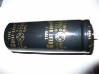
I have the supply cap here elna for audio 8 10000uF, 4 12000uF and 4 nichicon 22000uF 71V type-1 great supply, I don't found the datasheet of these cap. If I remember correctly I found these caps in a receiver Yamaha RX-V1 and I'm not sure if they are good cap see picture.
Thank you! maxpou
Given the number of output devices you have (16 IIRC), I think you can build a very capable 150W per channel amplifer (8 devices per channel, following the rule of thumb of 1 pair TO3P for each 40-50W).
Why 150 watts per channel while the other guys talking about 100 watts?
Big transformer will be a bit wasted, but the important thing is you have it - so just go for it. The only other expensive items are the smoothing caps and a case so you are already half way there.
I have the supply cap here elna for audio 8 10000uF, 4 12000uF and 4 nichicon 22000uF 71V type-1 great supply, I don't found the datasheet of these cap. If I remember correctly I found these caps in a receiver Yamaha RX-V1 and I'm not sure if they are good cap see picture.
Thank you! maxpou
Attachments
Hi Lazy Cat
Perhaps I have not your wallet to build four channelsand my preamp and cd player don't have a XLR connector.
Maxpou
One channel suitable to do the job, according to my DIY proposal, costs less than 50 USD, times four is 200 USD, plus input phase splitter 10 USD, times two is 20 USD, so all together 220 USD.
Look to the schematic I posted, there sits also RCA connector at the input.
What you are thinking right now, to build 2 x 100W amp with 2,5kVA power supply transformer is even more insane than Krell MRA.
Are you on a 110/120Vac supply?
I'll do the calculation that I adopt for close rated fusing, but at this lower mains voltage.
2500VA / 115Vac = 21.7Aac
That is the size of the close rated fuse that allows the transformer to drive a resistor load for ever at maximum power.
If we adopt approximately double that continuous current as the maximum peak current at start up then we have 43Apk and 115Vac (157Vpk) and this requires a 3r6 resistance in the transformer primary loop to ensure the start up peak current never exceeds 43Apk.
That is roughly the total resistance you need for the soft start resistor plus the primary circuit resistances.
With a transformer rated at 2.5kVA, the primary circuit resistances are likely to be <0r05
Just use a T20A and a pair of series connected 2r2r 20W power resistors bypassed after ~1/4second.
If you decide that you want to use a lower rated fuse than T20A for your house and personal safety, then increase the soft start resistance appropriately.
Split the transformer into separate piles of steel and copper and sell the piles as scrap.
Last edited:
Hi Lazy,
can you explain the two switches (one NO & one NC) that are labeled BAL?
Hi AndrewT
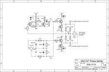
As drawn in the schematic the switch is in "Balanced" position, meaning XLR input cable (balanced) is allowed to be connected to the input of a bridged amplifier. When switch is in inverse position from drawn (upper closed, lower opened), than RCA input cable (unbalanced) could be connected.
What does the upper left circuit do? Is it an unbal to bal voltage converter?
Two mosfets on the left are forming simple unity gain voltage inverter. Four mosfets on the right are double unity gain non-inverter buffers, serving as impedance matching buffers of each phase of the drive signal to the bridged amplifier inputs.
Can you clarify where all the various GNDs connect to?
Yes, all GND points in this schematic forms star ground structure connected to the star ground of a bridged amplifier.
Regards, Andrej
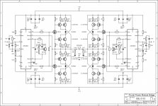
... and here's my schematic for one bridged-channel. It consist of two identical channels with LME49830 voltage driver plus 8 standard BJT outputs in BIGBT configuration. It is cheap and dirty.
Aha maxpou, the power of this bridged amplifier is realistic 400Wrms/8ohm or 800Wrms/4ohm, times two channels like this (stereo) is exact match to your super power transformer.

Thanks for post28.
Post29:
Is each half of the bridged amplifier capable of driving a 2ohms speaker? and 400W into 2r0 and ~750W into 1r0? To result in a 800W amp suitable for 4ohm speaker.
But he has run out of devices. Your stereo suggestion uses 32 outputs and he states 8pairs of NPN/PNP outputs.
Post29:
Is each half of the bridged amplifier capable of driving a 2ohms speaker? and 400W into 2r0 and ~750W into 1r0? To result in a 800W amp suitable for 4ohm speaker.
But he has run out of devices. Your stereo suggestion uses 32 outputs and he states 8pairs of NPN/PNP outputs.
Last edited:
Thanks for post28.
Post29:
Is each half of the bridged amplifier capable of driving a 2ohms speaker? and 400W into 2r0 and ~750W into 1r0? To result in a 800W amp suitable for 4ohm speaker.
But he has run out of devices. Your stereo suggestion uses 32 outputs and he states 8pairs of NPN/PNP outputs.
800W/4ohm is exactly 5Ap (3,54Aeff) collector current per one output BJT. With this types of 2SA/SC this is possible withot any problem, also in a SOAR point of view. Child's play.
Correctly, for stereo amp he will need 32 of outputs, so he will buy some more pieces since these are really cheap. He will also need four LME's but these are cheap too. I don't see any problem to make this amp real as real could be.
Hi Guys,
after several days of reading on the power amplifiers here I chose the symasym 5.3 with the input cascode JFET, but I would like to know it is a good choice if I put 8 outputs pairs? I will make some mods like replace R31 by CCS, replace some transistor model. Somebody have a comments? Thank you! Maxpou
after several days of reading on the power amplifiers here I chose the symasym 5.3 with the input cascode JFET, but I would like to know it is a good choice if I put 8 outputs pairs? I will make some mods like replace R31 by CCS, replace some transistor model. Somebody have a comments? Thank you! Maxpou
Attachments
HI Andrewt,
I read the threads of Ostripper on this power amp topology he put 4 output pairs without big mod. What's the problem you see? Thank's Maxpou
The 5.3 symasym you post uses a low current VAS +EF2 output stage.
2-pair is about tops- here.
The forums "Badger" is also an EF2 , but the VAS is to-126 and can be
run at near 10ma plus be generously heatsinked.
Most of the other EF2's (forums most common output stages), are under
rated with to-220 drivers running 4 or more pairs of outputs.
The "slew" series is an EF3 with outputs !!!... for drivers. Here , you could run
10 pairs if you wanted and have driver SOA left over.
The EF3 also "isolates" the VAS from the current stage - having 100K
current gain.
You would have "droop" and higher distortion just doubling the output
pairs on the original 5.3 symasym.
OS
Hi Os,
thank you for your answer, I would have liked to use your SLEW design but it's physically impossible in my amp chassis. I will try the symasym with 5 pairs ops and I will work for the sound quality.
http://www.diyaudio.com/forums/soli...-next-generation-supersym-26.html#post3885346
I would like to have a suggestion for my soft start with one or more cl60 or resistor?
thank you! Maxpou
- Status
- This old topic is closed. If you want to reopen this topic, contact a moderator using the "Report Post" button.
- Home
- Amplifiers
- Solid State
- Power amp suggestion