RF grounding
Grounding things at 50/60Hz, 20kHz, 20MHZ is like visiting other planets. To keep it simple, I hadn't brought up the RF stuff. Running the shield the extra mile to the star ground, I find stray magnetic fields from the power transformer add hum. For RF on the input, the impedance of traces and the PCB ground wire are high enough that you need extra bypass caps or a filter to properly deal with it. In troublesome systems, I use Coilcraft ISDN transformers as common-mode chokes, as shown in this Jensen app. note AS072: http://www.jensen-transformers.com/as/as072.pdf
I find RF can come into a power amp many ways:
Rectifier switching transients and power transformer inter-winding capacitance already put some RF and line garbage at point "8".
Loudspeaker cabling is a wonderful dipole antenna and I find it brings in RF right to the output transistors. Much worse in MOSFET amps, I put common-mode ferrites on my speaker wiring to bring this down.
Ultimately, I use RF bypass caps to the chassis in strategic places. My 900MHZ cordless phone makes a great signal generator...
Do you have a reason why the shield for the input would go to point 1 rather than directly to 7 (the quiet star point)? As far as I can see, by doing it this way, the RF common mode currents on the shield get fed directly into the base of the LTP transistor via the input filter cap.
Grounding things at 50/60Hz, 20kHz, 20MHZ is like visiting other planets. To keep it simple, I hadn't brought up the RF stuff. Running the shield the extra mile to the star ground, I find stray magnetic fields from the power transformer add hum. For RF on the input, the impedance of traces and the PCB ground wire are high enough that you need extra bypass caps or a filter to properly deal with it. In troublesome systems, I use Coilcraft ISDN transformers as common-mode chokes, as shown in this Jensen app. note AS072: http://www.jensen-transformers.com/as/as072.pdf
I find RF can come into a power amp many ways:
Rectifier switching transients and power transformer inter-winding capacitance already put some RF and line garbage at point "8".
Loudspeaker cabling is a wonderful dipole antenna and I find it brings in RF right to the output transistors. Much worse in MOSFET amps, I put common-mode ferrites on my speaker wiring to bring this down.
Ultimately, I use RF bypass caps to the chassis in strategic places. My 900MHZ cordless phone makes a great signal generator...
prairiemystic
in your latest diagram you have shorted out the front end isolation resistor. Any reason for that? You should not do that because the way its connected now, all the noise generated between the input side of that resistor and the other side is effectively in series with the input signal - you actually will be injecting noise into the signal chain.
Re the RF point raised a bit earlier. If you have 900MHz on the input line, moving the screen connection from the input side to the commin 0V side is not going to help for the reasons I stated above (exchange one problem for another). Best thing is a small cap (say 1nF) from the screen to the amplifer chassis. This technique is used in a lot of commercial amps. This effectively shorts the screen to the chassis at RF but does not affect things at the audio freqeuncies.
post 7 diagram.
I wish everyone would draw their schematics this way. You can see where all the signals should be going.
I still have doubts about where 2a is better located. Should it have a dedicated return to 7, possibly with a resistor to the PCB power ground or connect to Signal Ground or to -ve supply rail??
The Signal Ground (1&2) to Audio Ground (7) is shown conventionally. Leach and others suggest that the RCA barrel be connected to 7 rather than from 2 to 7.
I have found this more resistant to hum with most amplifier layouts.
Leach is an advocate of the 10r, low inductance, connection between Signal Ground and Power Ground.
Can you explain in more detail why this makes problems worse?
No, I don't think the RCA barrel should go to 7. 2 is the right place for it with or without the 10 Ohm resistor.
The 10R does not make things worse - it just prevent ground loops if you end up shorting the barrel to GNDS on the chassis. As mentioned in an earlier post, if you short it out and your amp remains silent, you can remove it safely. I always put it in as a matter of course
The 10R does not make things worse - it just prevent ground loops if you end up shorting the barrel to GNDS on the chassis. As mentioned in an earlier post, if you short it out and your amp remains silent, you can remove it safely. I always put it in as a matter of course
By removing it, do you mean adding in a shorting link to replace the 10r resistor?The 10R .............. As mentioned in an earlier post, if you short it out and your amp remains silent, you can remove it safely. I always put it in as a matter of course
If this shorting link is added, would you also remove the external 2 to 7 link?
Any thoughts on 2a?
Please explain why RCA barrel to 7 is not a good alternative to 2 to 7.
As I see it the amplifier is an instrument that measures the Vdiff at the RCA terminal, multiplies it (or other manipulation) and sends it's answer to the speaker.
It does it's best to make that speaker signal as close a match to the RCA signal as it can possibly be.
If the NFB, the RF filter cap and the Rin all return via the screen to the RCA barrel, then that helps ensure that the amplifier is measuring the RCA signal.
Now we tell the amplifier how to reference that RCA signal to the Speaker Return. We reference both locations to the Main Audio Ground.
Why is this logic wrong or at least not advised?
Last edited:
Grounding things at 50/60Hz, 20kHz, 20MHZ is like visiting other planets. To keep it simple, I hadn't brought up the RF stuff. Running the shield the extra mile to the star ground, I find stray magnetic fields from the power transformer add hum.
OK, is this with a toroid or EI as the mains transformer? This is a mod I did on my Xindak amp - routing the screen from the input phono direct to the star point which is a bolt on the bottom of the chassis. I haven't noticed any increase in hum but boy has the transparency gone up - sound stage is much clearer now, feels like the noise floor dropped. I A/B'd it, with an output attenuator, comparing it to a direct connection to my active speakers.
I find RF can come into a power amp many ways:
Rectifier switching transients and power transformer inter-winding capacitance already put some RF and line garbage at point "8".
Yep, especially with a toroidal - I find these have around 500pF capacitance between the windings.
Loudspeaker cabling is a wonderful dipole antenna and I find it brings in RF right to the output transistors. Much worse in MOSFET amps, I put common-mode ferrites on my speaker wiring to bring this down.
Curious to know why MOSFETs are worse in this regard? At first thought I'd have imagined they'd be better than bipolars due to typically having wider bandwidth. Is this with both laterals and verticals?
this corresponds to my last post. Measure what is at the RCA input terminal and send the result to the speaker......... This is a mod I did .......... - routing the screen from the input phono direct to the star point ............. I haven't noticed any increase in hum but boy has the transparency gone up - sound stage is much clearer now, feels like the noise floor dropped. I A/B'd it, with an output attenuator, comparing it to a direct connection to my active speakers.
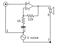
Input stage grounding
To better understand the input stage grounding (1, 2), I redrew things.
Overall, power amps are differential amplifiers, with the NFB divider resistors referencing things to ground.
Noise on 1, 2 appears somewhat common-mode, depending on its relation to the output voltage (in or out of phase).
So I would not connect 1, 2 to 3, 4 but instead straight to the star point 7. The 10 ohm resistor to help with ground loops I'd leave in, as it's easy enough to bypass.
W.M. Leach has used at least three different techniques for grounding (mildly confusing) with resistor R51 (82 ohms) in but shorted by a wire run to "7", as I drew in my earlier post:
"The circuit board has two ground leads, both of which connect to the central power supply ground. One lead grounds the signal reference points for the diff amp input stage. The other grounds the power supply decoupling capacitors and provides a ground reference for the protection circuit. R51 connects the two ground leads together on the circuit board. This resistor is small enough to look like a signal short circuit between the two grounds but large enough to force the currents in the two grounds to flow to central ground through the separate wires. This helps to prevent hum induced by power supply ripple currents in the ground system."
Attachments
Your diagram above and your conclusions are by and large correct I'd say. However, what we have been concerned with in the preceeding pages is the situation where there is noise injected between 1 and 2 on your diagram above. This happens, typically, when the output stage decouplers are connected between 1 and 2 as a result of misguided PCB layout errors, or just plain oversight. In these cases, noise is injected in series with the input signal. If we follow strict layout rules and order the decoupling capacitors correctly, this noise problem is largely circumvented. Keep in mind there are a number of noise coupling mechanisms at work in an amplifier. The danger with connecting the input ground to the star point in my view is that you really have to be certain you are not injecting anu noise into the ground connection - through ground impedance coupling (as described above), or through magnetic induction. In these cases, you then move the noise generator so that it sits between 1 and 2 above.
this corresponds to my last post. Measure what is at the RCA input terminal and send the result to the speaker.
Precisely. So don't run the input signal RCA gound to the star ground!
")
best ground location for 2a?
I'm not having much luck with the best ground location for 2a. On the Leach amp, it's the cascode reference point. On the Blameless, it's the EF buffer collector. The node (ground) current is a few milliamps of DC with signal AC.
The damn cascode is great for video, I think 20MHz bandwidth here so it needs RF bypass too. The big cap is for the zener noise.
If you connect 2a to input ground 1,2 then the DC adds an offset 0.1V at 10mA with signal AC on that as well.
If you connect 2a to power ground 4 then the ground bounce there gets pumped back into the cascode.
If you connect 2a to star ground 7 then you just need HF bypass to 1,2.
Any ground wire runs (estimating) 16ga/10" are about 300nH and 0.0033 ohms. Doubles at 20kHz and 15x at 1MHz due to skin effect.
I'm starting to favour having the star ground on the pcb, since all the wiring is less.
Regarding the input shield ground point: It might also depend on the particular layout, i.e. the physical distance between 7 and 2, and whether or not extending the input RCA ground to 7 would appreciably increase the loop-area formed by the input signal and ground conductors. More loop area would enable more currents to be induced by time-varying EM fields. My guess would be that the input ground and signal conductors should "terminate" as close to each other as possible.
Regarding the input shield ground point: It might also depend on the particular layout, i.e. the physical distance between 7 and 2, and whether or not extending the input RCA ground to 7 would appreciably increase the loop-area formed by the input signal and ground conductors. More loop area would enable more currents to be induced by time-varying EM fields. My guess would be that the input ground and signal conductors should "terminate" as close to each other as possible.
I agree.
I read this last night and thought it meant "refer the amplifier input to the RCA input socket".Precisely. So don't run the input signal RCA ground to the star ground!
But, today re-reading it seems to be saying something else.
Bonsai,
please restate what you recommend.
for a monoblock, this works well, almost perfect.I'm starting to favour having the star ground on the pcb, since all the wiring is less.
Try incorporating two or more channels inside a common case and/or fed from a common dual secondary transformer and the on board multiple PCB stars suddenly become totally inadequate. I believe the less than perfect arrangement must have a common Main Audio Ground somewhere between all the clients it serves and with all connection as short as possible.Each individual return to the Main Audio Ground should run alongside the Flow that that individual circuit needs to maintain that small loop area we are talking about.
Here:-
If you run the signal wire to the amplifer input and then the amplifer end of the screen to the star ground, I think you are asking for problems.
The RCA socket must be fully isolated from the chassis. The screen and the signal wire must terminate on the amplifer PCB signal ground. In my case, as stated earlier, I usually put a low value resistor between the input signal ground and the main amplifer PCB ground.
If the grounding order on the amplifer PCB is in line with Prairiemystic's earlier diagram (where I commented that it looked good), then there should be no hum.
I have a big power amp (250W per channel) and a pre-amp using this grounding technique. With volume full up there is 0 (zero) hum out of the speakers. I also checked with a scope on the amp output - (1mV/div) - I cannot see anything.
For me, this works very well.
I also had an ETI amp I built a few years ago. for the power supply, I used the transformer and rectifier assembly from a Marantz 240B amplifer. Input wiring as I described above. Also zero hum.
Last edited:
The screen and the signal wire must terminate on the amplifer PCB signal ground.
The problems may be different then, but certainly this brings problems which are quite audible. In pro audio, the ground and screen is pin1 of the XLR and terminating this on the PCB is a no-no. So we must trade off potential induced noise within the amp for certain RF induced noise coming directly onto the PCB. I can only suggest listening to both, then choosing. I've always chosen terminating the screen direct to the star point when I've listened - no difference between them in hum but loss of clarity when terminated on the PCB.
- Status
- This old topic is closed. If you want to reopen this topic, contact a moderator using the "Report Post" button.
- Home
- Amplifiers
- Solid State
- Power Amp PCB design, grounding