I find I'm in agreement with prairiemystic - not having a star grounding scheme for this board is a step backwards sonics-wise. An audio power amplifier is not an RF system, it has far higher dynamic range requirements (>110dB) than any RF system I know of so requires careful control of ground currents and measures taken to mitigate RF from external sources in order to achieve the most transparent sound.
Star ground as in all ground connections should meet in 1 single point? or something in between - I find that compromise is a must.
- This I think something that can be done, but with the density of this board, I think the result would be worse compared to the ground plane solution.
- I'm not aware of anyone being unhappy with the SNR of the design - but then again I haven't asked.
I have experience of making low noise PSU designs feeding an analog stage with the noise floor <-110dBm/Hz... done with full ground planes.
I think the main problem for most power amp designs is to manage the ripple current in the rail capacitors, and making sure that the current does not pass the small signal stage... this can be achieved using either of the two grounding schemes (IMO)
\\\Jens
Conrad,
had a quick look through chap. 3 of "Electromagnetic Compatability Engineering", I belive 3.2.5 is the relevant part. Basicly the best place to connect to Chassis ground is in the IO area of the PCB (where any IO connectors are). This is a very basic summerisation of what is quite an involved chapter (3. Grounding).
Ground planes with slots to control current (if required and if you know where to put them) have been used for analogue design for years, and if done right provide the best of both worlds (Hi frequency EMC shielding, and providing a return path that is low impedence and as near an equipotential point as possible).
Dear Marce,
You mean one unbroken total plane? Or several groundplanes for low and high signal and connected at a single point?
With kind regards,
Bas
Star ground as in all ground connections should meet in 1 single point? or something in between - I find that compromise is a must.
Yeah, compromise is the order of the day, there are degrees of that
 Have a look at my blog for some examples of what I did with the active speakers I have.
- This I think something that can be done, but with the density of this board, I think the result would be worse compared to the ground plane solution.
And the need for high density is greater than the need for good sound?
I'm fairly sure that partitioning your grounds into signal, power, decoupling, input and output (that's five points on the star) would gain you some worthwhile improvements in transparency than what you've currently got.- I'm not aware of anyone being unhappy with the SNR of the design - but then again I haven't asked.
I wasn't referring to measured figures - I don't myself have an AP so haven't made any measurements of things that change when the grounding changes. But I have heard improvements in several amps where I've taken them apart and rewired the grounds. No amp that I own have I found optimal grounding on!
I have experience of making low noise PSU designs feeding an analog stage with the noise floor <-110dBm/Hz... done with full ground planes.
What would that be in an audio bandwith and in uV?
I think the main problem for most power amp designs is to manage the ripple current in the rail capacitors, and making sure that the current does not pass the small signal stage...
You have two large electrolytics on your board, but at a first glance you run the current between them all around the houses through the ground plane. That's not going to sound very sweet methinks. With a ground plane its very hard to work out what the current density will be at various points. Much better having a dedicated connection just between those two which then runs back to the star.
These days most boards I design have an unbroken and quite often multiple gound planes, but these are mostly analoge/ digital mixed and very dense. When doing less dense design but quite often more complex such as SMPS, Servo controll, Audio you can tailor the ground plane and more criticaly component layout to achieve the best results. The point of star ground is to create area's of an equipotential, ie 0V and achieve an EMI stable design. IMO the spindly leg ground schemes do not achieve this, quite often resistors next to each other have quite thin tracks connecting them seperatly to the star point. This creates an inductive and resistive path between both GND points which in times of current change will create different voltages at these points, a source of noise in audio, a disaster in some control systems, whereas using localised planes gives the best of both world.
If you can get a copy the book by Henry Ott I emntioned earlier is a good start (Chap 3) into the complexities of grounding. Its also one of those fun subjects that can get quite emotive, with some quite polorised views.
If you can get a copy the book by Henry Ott I emntioned earlier is a good start (Chap 3) into the complexities of grounding. Its also one of those fun subjects that can get quite emotive, with some quite polorised views.
Just so I understand, Jens I didn't know you need insulated standoffs (spacers) on your design. But the pcb now has isolated mounting bolt holes? Two ground wires from pcb to cgnd, loudspeaker return to cgnd?
I am away this weekend but could do a sketch, it might be easier.
I am away this weekend but could do a sketch, it might be easier.
These days most boards I design have an unbroken and quite often multiple gound planes, but these are mostly analoge/ digital mixed and very dense. When doing less dense design but quite often more complex such as SMPS, Servo controll, Audio you can tailor the ground plane and more criticaly component layout to achieve the best results. The point of star ground is to create area's of an equipotential, ie 0V and achieve an EMI stable design. IMO the spindly leg ground schemes do not achieve this, quite often resistors next to each other have quite thin tracks connecting them seperatly to the star point. This creates an inductive and resistive path between both GND points which in times of current change will create different voltages at these points, a source of noise in audio, a disaster in some control systems, whereas using localised planes gives the best of both world.
If you can get a copy the book by Henry Ott I emntioned earlier is a good start (Chap 3) into the complexities of grounding. Its also one of those fun subjects that can get quite emotive, with some quite polorised views.
Dear Marce,
I have this book in real (paper)
In a recent AES course by Guido Tent and Bruno Putzeys about this subject, they stated as well, that a ground-plane should by even without any slots. Even for power amplifiers. The trick is to give every stage the right (ground) reference. However I am very afraid for humm and noise in this configuration. According to Bruno and Guido a full ground-plane for power amplifiers is far superior to old fashion star-gounding. What is your feeling about this? And even one step further, in case of 4 or 6 layer boards, what about Power Planes in power amplifiers?
With kind regards,
Bas
In a recent AES course by Guido Tent and Bruno Putzeys about this subject, they stated as well, that a ground-plane should by even without any slots. Even for power amplifiers. The trick is to give every stage the right (ground) reference. However I am very afraid for humm and noise in this configuration. According to Bruno and Guido a full ground-plane for power amplifiers is far superior to old fashion star-gounding. What is your feeling about this? And even one step further, in case of 4 or 6 layer boards, what about Power Planes in power amplifiers?
Hi Bas - do you have a link to this as I'm surprised that Bruno would advocate ground planes over star grounding for normal power amplifiers. Perhaps he was talking about class D where the high frequency performance is more critical?
i have a question about the wire distance, i know that the lenght should be as short as possible, i just want to know, how will the wire start to affect the preformance of the amp??
It depends which wire you're talking about. All wires are antennas, they radiate and pick up RF - the longer the wire, the more effective the antenna down to lower RF frequencies. Some wires are unavoidably long - like speaker wires - these affect the sound not only by adding DC resistance and inductance, but also by sending RF energy back into the amp. Once RF has found its way into an amplifier, the sound quality will generally degrade, depending on the details of the particular amp design. In my view, valve amps are less susceptible to RF-induced degradation than solid-state.
I would think ground planes in audio would be of benefit in the digital part of the signal chain, or in class D. However, I can attest to the fact that in consumer audio class D, the big guys here in Japan put much store in being able to manufacture class D amplifiers with single sided boards for reasons of cost. For linear amplifiers, I doubt that a full ground plane is necessary. Although you have worry about trace inductance, remember that in a typical linear amp input signal rise time is limited. The best you will see is 1-2uS, with rise time figures higher than this the norm. A 5A current transition in 1us across 100nH of inductance will give rise to a 0.5V drop. This is an extraordinary di/dt to find in a linear amp - in fact, its not possible. In a class d amp of course, this is possible to see in the output stages.
It depends which wire you're talking about. All wires are antennas, they radiate and pick up RF - the longer the wire, the more effective the antenna down to lower RF frequencies. Some wires are unavoidably long - like speaker wires - these affect the sound not only by adding DC resistance and inductance, but also by sending RF energy back into the amp. Once RF has found its way into an amplifier, the sound quality will generally degrade, depending on the details of the particular amp design. In my view, valve amps are less susceptible to RF-induced degradation than solid-state.
thx yr explanation
so i need to pay more attention to the wire length that going into the amp, right?
thx yr explanation
so i need to pay more attention to the wire length that going into the amp, right?
Normally connections to amp inputs are via screened cables. If the screening is good (note that doesn't mean a boutique cable) then the screen becomes the antenna rather than the input wire. Then the issue is how well the amp ignores RF on the ground terminal of its input. Plenty of amps are rather poor at this. The length of the input wire is of secondary importance to this factor.
Controling EMC is best done at the PCB level. Spndly tracked ground connections are worse for this. as I mentioned earlier STAR point grounding seems to have got distorted into high inductance spider leg routing (a nice antenna).
From my experience with analoge/ digital PCB layout ground planes are best, these can be split to control currents, but this is not for the faint hearted or the inexperienced as more problems can be caused.
From my experience with analoge/ digital PCB layout ground planes are best, these can be split to control currents, but this is not for the faint hearted or the inexperienced as more problems can be caused.
Hi Bas - do you have a link to this as I'm surprised that Bruno would advocate ground planes over star grounding for normal power amplifiers. Perhaps he was talking about class D where the high frequency performance is more critical?
Dear Abraxalito,
Sorry I don't have a link since it was a real classroom and not virtual. I do have the prints from the powerpoint presentation, and I will ask permission to post them.
It is clear Bruno is HF and class D orientated, however his advice for ground-planes over star-ground remains also for linear class A and A/B amplifiers.
In short I will try to resume his message.
-Don't try to prevent ground-loops, they are there anyway. However try to prevent them from flowing in your audio circuits. This by choosing the right ground reference point on different places in the audio circuit. Problems would be totally solved if you kept all line differential on the PCB.
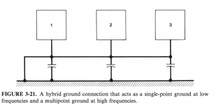
A very interesting approach can also be (not from Bruno's class) Chapter 3.2.4 from Electromagnetic Compatibility Engineering (2009 Malestrom) called hybrid grounds. Combine the ground-plane with the star ground. Obvious you keep your star-grounding as u do conventionally. Try as much as possible point to point. However ground the same individual circuits with a capacitor to the ground-plane.
In this setup, for low frequencies you control the currents, the higher frequencies choose the path of the least inductance through the ground-plane. As bonus the whole PCB is better shielded for EMI by the addition of this ground-plane.
I never tried out the above yet, but I like he approach.
However, my first choise would be keep al audio tracks differential and avoid any audio part need to reference to the ground-plane. And thun use a whole ground-plane for the whole circuit.
With kind regards,
Bas
Attachments
Last edited:
Thanks guys for your input! Bonsai, I drew the grounds in the sequence you list, and got puzzled. Are you saying a star point doesn't work well? I'm not sure about thinking of it as a series run- is this on a microscopic level? I am aware of voltage gradients on high current pcb pads (and even a bolt with stacked lugs), in practice all nodes can never be equipotential. Maybe this is the (lug or wire) sequence at the star point? That I can understand.
Overall, I find two techniques are popular:
1. The star point is on the amp chassis as a single bolt, with the amp PCB having two ground wires (quiet gnd and noisy gnd) tied to it. With 5-15 wires it gets crazy and I dislike the extra wiring inductance. I've 'scoped a lot fuzz, despite a using a big bolt or copper bus wire. The Leach amps use this technique.
2. The star ground point is on the amp pcb, with a single ground wire to the PSU. The loudspeaker and zobel ground also connect to this pcb star point. Silicon Chip magazine has been using this guessing 10 years, in the Studio 350 and ULD Mk2 etc. I like this scheme a lot and would only add RF bypass to it.
On the odd-ball ground point, my reckoning is AC on the cascode decoupling caps/zener ends up modulating the transistor's base, so I'm not seeing how the diff. amp doesn't react. It's not common-mode noise?
Hello prairiemystic,
Does the picture you have posted in http://www.diyaudio.com/forums/solid-state/168202-power-amp-pcb-design-grounding.html#post2211375 show the order in which the 0V signal can be taken from a "linear" trace instead of a star point? Does it mean that it would be better to run a single trace from the 0V filter capacitor "8" and branch it into several traces going to the different parts of the amplifier? If this is the case, it looks like the 0V branch going to the input "1" will have a different (variable) voltage than the 0V at the filter capacitor "8" due to the (small) resistance of the trace and large currents passing through common parts of the trace. Is this ok? Any comments are appreciated.
Thanks,
Alex
I always have a connector very close to the power suply capacitors ground and tie this to chassis ground. Its the most logical place.
I have never had any hum problems using this method.
Hi Bas,In short I will try to resume his message.
Only just saw your reply from a couple of weeks ago!
Yes I agree about the differential method - I'm designing a DAC (at the 'in my head' stage) at the moment and I'm going to do it as differential as possible. So given that we go for a balanced audio path, the ground plane becomes power ground only. For that we always do want low inductance, but then with true differential signals we don't need to decouple to the ground plane at all as no current sinks there. So it just becomes a screen!
A very interesting approach can also be (not from Bruno's class) Chapter 3.2.4 from Electromagnetic Compatibility Engineering (2009 Malestrom) called hybrid grounds. Combine the ground-plane with the star ground. Obvious you keep your star-grounding as u do conventionally. Try as much as possible point to point. However ground the same individual circuits with a capacitor to the ground-plane.
Have you ever seen pictures of the inside of the Berkeley Alpha DAC? This is reputed to sound very good, they appear to use what I call 'island ground planes' - just keep the ground planes small, limited to small sections of the circuit. I seem to recall Paul Frindle also recommending this method in one of his AES papers.
However, my first choise would be keep al audio tracks differential and avoid any audio part need to reference to the ground-plane. And thun use a whole ground-plane for the whole circuit.
So then the ground plane is just connected to power-0V ? And only acts as a shield, not carrying any power supply current?
Hello prairiemystic,
Does the picture you have posted in http://www.diyaudio.com/forums/solid-state/168202-power-amp-pcb-design-grounding.html#post2211375 show the order in which the 0V signal can be taken from a "linear" trace instead of a star point? Does it mean that it would be better to run a single trace from the 0V filter capacitor "8" and branch it into several traces going to the different parts of the amplifier? If this is the case, it looks like the 0V branch going to the input "1" will have a different (variable) voltage than the 0V at the filter capacitor "8" due to the (small) resistance of the trace and large currents passing through common parts of the trace. Is this ok? Any comments are appreciated.
When you make a star ground point (on a PCB or chassis bolt), it ends up being a stack or line of things to connect. This sequential or "linear" view as drawn is from using a microscope to exaggerate things, as a trace a few mm in the wrong place can add distortion. You are right, the quiet ground "1" should have a dedicated return to the system star point "7", i.e. done in the Leach amplifiers. "8" is considered a dirty point due to the high capacitor ripple currents and so "7" is the actual system star ground.
Here is an updated pic of a (overall) grounding scheme that I see a lot. Two PCB ground wires are run (quiet and noisy). Other designs move the star ground "7" onto the PCB, instead of off PCB on a chassis bolt. I'll post a pic of a PCB layout that did that.
Attachments
Here is an updated pic of a (overall) grounding scheme that I see a lot.
Do you have a reason why the shield for the input would go to point 1 rather than directly to 7 (the quiet star point)? As far as I can see, by doing it this way, the RF common mode currents on the shield get fed directly into the base of the LTP transistor via the input filter cap.
PCB star ground implementation
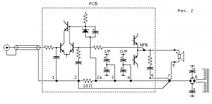
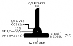
Here is my sketch of a power amp PCB star ground implementation, taken from Silicon Chip Magazine designs, showing ground point "7" (in my other sketches) moved onto the PCB.
My complaint would be having the loudspeaker and Zobel return connected to the PCB. This means high currents flowing in the wiring from the PCB 0V point back to the PSU, which is not optimal.
Attachments
- Status
- This old topic is closed. If you want to reopen this topic, contact a moderator using the "Report Post" button.
- Home
- Amplifiers
- Solid State
- Power Amp PCB design, grounding