Attachments
Hey, don't link 3000X4000pixels pics, reduce size to 1024 X whatever frame. It creates problems in viewing. Resized and loaded back as an attachment.

Rod Elliot's amp project =)
P3A integrated amplifier with Death of Zen preamp (DoZ).
P3A integrated amplifier with Death of Zen preamp (DoZ).
Attachments
Here is a write up of my pre-amp, the X-Altra Mini One, in pdf format - click on the 'Line Preamplifiers' tab - with pictures and circuit details.
hifisonix.com | Audio Design and Music Reviews
hifisonix.com | Audio Design and Music Reviews
How about two monoblocs running 6A bias current and pushing 5.6 kW continuous into 4 Ohms resistive. Makes your experience at a Pink Floyd concert pretty realistic.
Hey Nico, do You want us all to get def?
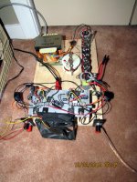
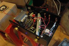
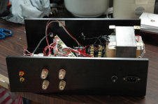
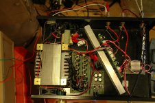
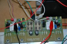
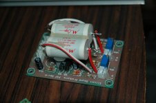
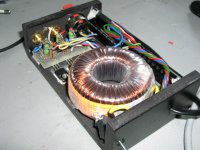
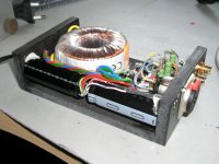
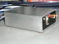
this is my some project pic,s hope u like ...
pic,s
pic,s
Attachments
-
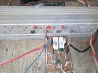 Photo0343.jpg765.3 KB · Views: 319
 -
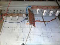 Photo0347.jpg787 KB · Views: 442
 -
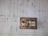 Photo0339.jpg805.9 KB · Views: 668
 -
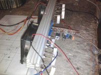 Photo0346.jpg290.2 KB · Views: 264
 -
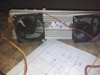 Photo0350.jpg952.9 KB · Views: 262
 -
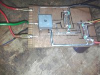 Photo0292.jpg332.2 KB · Views: 274
 -
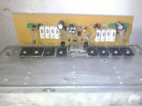 Photo0289.jpg753.6 KB · Views: 389
 -
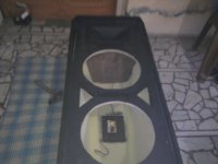 Photo0338.jpg559.8 KB · Views: 263
 -
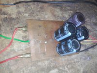 Photo0293.jpg966.7 KB · Views: 250
 -
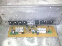 Photo0291.jpg786.3 KB · Views: 481
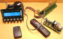
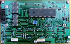
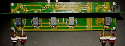
The ultimate control unit!
Behold a useful "tool" for each DIYer who takes his hobby seriously! A different control unit for preamplifiers and integrated amplifiers!
Here is the full article: welcome to* The Electronic Audio Labs web magazine
Behold a useful "tool" for each DIYer who takes his hobby seriously! A different control unit for preamplifiers and integrated amplifiers!
Here is the full article: welcome to* The Electronic Audio Labs web magazine
Attachments
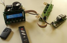
Few pictures more, and a small description
What it makes this control unit to differ from others, is not the common RC5 remote control receiver/decoder that includes, but:
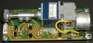
1) its ability to manage noiseless Latching Relays which can be used as input selectors, like in famous Hi-End preamplifiers (e.g. Pass Labs X.01).
You could consider Latching Relays like an expensive rotary switch.
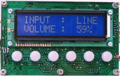
2) its ability to control the ALPS RK27 Blue Velvet volume potentiometer digitally, either thru the remote control handset or thru the 2 push-button switches mounted on the control board, while, at the same time it shows the volume value (depending on the rotation angle of ALPS) on the LCD display thru the second mono potentiometer (connected at the Analog input RA0 of MCU) that is joined to the shaft of ALPS. Therefore, no need for bulky volume knobs, holes, print of circular numerical scales on front panel etc. The volume control unit can be hidden inside the case of preamplifier.
You can read many other details and instructions, and you can download schematics and PCB layouts ready for direct printing on artwork films from: http://www.eal.gr/MICROS.htm
Sorry guys, but the article is too long, and i wouldn't like to spend precious space from the diyAudio forum servers.
Fotios
What it makes this control unit to differ from others, is not the common RC5 remote control receiver/decoder that includes, but:
1) its ability to manage noiseless Latching Relays which can be used as input selectors, like in famous Hi-End preamplifiers (e.g. Pass Labs X.01).
You could consider Latching Relays like an expensive rotary switch.
2) its ability to control the ALPS RK27 Blue Velvet volume potentiometer digitally, either thru the remote control handset or thru the 2 push-button switches mounted on the control board, while, at the same time it shows the volume value (depending on the rotation angle of ALPS) on the LCD display thru the second mono potentiometer (connected at the Analog input RA0 of MCU) that is joined to the shaft of ALPS. Therefore, no need for bulky volume knobs, holes, print of circular numerical scales on front panel etc. The volume control unit can be hidden inside the case of preamplifier.
You can read many other details and instructions, and you can download schematics and PCB layouts ready for direct printing on artwork films from: http://www.eal.gr/MICROS.htm
Sorry guys, but the article is too long, and i wouldn't like to spend precious space from the diyAudio forum servers.
Fotios
Attachments
Last edited:
Yes, the motorised pot can be used to control the current to the LEDs.I will pair it with a Lighter note as a way of adding LDRs a remote control and the ability to see the percentage of volume.
But the pot circuit must allow all 6 pins to be intercepted for the LED current control signals.
If the pot is soldered in with a common ground for both return pins, then you will need to modify the PCB slightly.
mmm I kinda like it Fotios, maybe I will pair it with a Lighter note as a way of adding LDRs a remote control and the ability to see the percentage of volume.
You should be able to use the ALPS motorized pot. for the brightness control of LEDs needed for the LDRs, instead for the signal level control. Taking into account the LED Vf=2V (3V for high brightness LEDs) i am wondering: where you can find a linear motorized pot. of 2 X 500 Ohms? Be it so 2 X 1K? The smallest value offered on the market is 2 X 10K.
Fotios
I have just realized that we would need to have the same 100k log dual pot, but I have just seen too that it has already a 100k alps.Yes, the motorised pot can be used to control the current to the LEDs.
But the pot circuit must allow all 6 pins to be intercepted for the LED current control signals.
If the pot is soldered in with a common ground for both return pins, then you will need to modify the PCB slightly.
For the pinout I am aware that we may have to isolate all 6 pads and cut the necessary traces, for optimal isolation.
Fotios, the pot is not intended to work directly with the LDR, but with the boards Uriah is offering for the simpler LDR vol. control or for the Lighter note. They need a 100k pot, so adding this external one should do the job.
- Home
- Amplifiers
- Solid State
- Post your Solid State pics here