Hi Edmond,
First rate job there... the construction quality looks excellent.
How do you reckon they would compare sound wise with todays offerings ?
")
In the mid 70's is when I first started dabbling in electronics... my first project, a traffic light controller for a model railway using a 7413, 7490 and 7441... and then I was hooked
First rate job there... the construction quality looks excellent.
How do you reckon they would compare sound wise with todays offerings ?
In the mid 70's is when I first started dabbling in electronics... my first project, a traffic light controller for a model railway using a 7413, 7490 and 7441... and then I was hooked
tape deck
Hi Mooly,
Thank you for your compliment!
>How do you reckon they would compare sound wise with todays offerings?
Sorry, I can't answer that question. It's long ago I've listened to this machine and all documentation is lost.
But I do know that this tape deck was competitive with studio recorders in those days. Not surprisingly, as most of the mechanical parts, including the tape heads, came from the 'scrapyard' of Phonogram (the record division of Philips). The record and playback amps were not that advanced, though the head amplifier was comprised of multiple parallel trannies in the input stage.
What made this machine so special was a high speed automatic seek mechanism. You could program it by setting the thumb-wheel switches. When set to 1000 for example, the tape was advanced by 1000 seconds (playing time, of course) with high speed and then started playing without further ado.
BTW, The counter was comprised of four good ol' SN75192 (a synchronous up/down counter) and four SN7485 (a magnitude comparator).
Oh, I almost forget, also 4x HP5082-7300 (a dot matrix display), which cost an arm and a leg in those days (Fl. 450.00).
Cheers,
E.
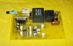
Here's my tape recorder built in the seventies. Second picture is from the control-logic (DTL ICs!) for tape tension, electronic breaks and seek function (calibrated in seconds).
Cheers,
E.
Now THAT is what I call engineering! Very good indeed
Now THAT is what I call engineering! Very good indeed
It's brilliant isn't it
Not a PIC in sight too.i apologize if this doesent qualify
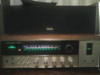
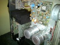
I apologize if this does not qualify but I love this radio it sounded great when I got it for about about three weeks and has quite a few gremlins in it now from old age but I just keep on replaceing parts it is curently playing beautifully again for now. This is my Harmon Kardon ta600 from 1976 and has I believe what you call dual jfet and draws 500watts from the wall. Output wattage is currently unknown but I know it will push a two ohm load like its not their. The big caps are dead but the hum is not that noticeable yet and I have already orderd new 13000mfd 40wvdc caps. All in all I really like this piece. Opinions? Comments? Please ask and do tell
I apologize if this does not qualify but I love this radio it sounded great when I got it for about about three weeks and has quite a few gremlins in it now from old age but I just keep on replaceing parts it is curently playing beautifully again for now. This is my Harmon Kardon ta600 from 1976 and has I believe what you call dual jfet and draws 500watts from the wall. Output wattage is currently unknown but I know it will push a two ohm load like its not their. The big caps are dead but the hum is not that noticeable yet and I have already orderd new 13000mfd 40wvdc caps. All in all I really like this piece. Opinions? Comments? Please ask and do tell
Attachments
Last edited:
My DIY Integrated amp,150W,2ch with remoter control.Non-loop NFB desigh.
An externally hosted image should be here but it was not working when we last tested it.
An externally hosted image should be here but it was not working when we last tested it.
An externally hosted image should be here but it was not working when we last tested it.
Wow - that does look nice Zhubin. Care to shre some of the design detials with everyone?
With schematic!
Regards
Hi Zhubin
Wow, that metal work and case looks really sweet.
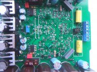
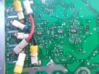
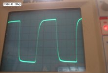
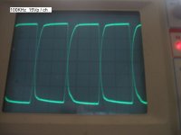
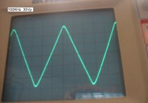
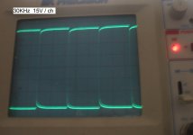
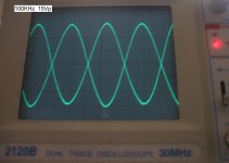
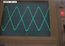
Looks a whole lot better than mine. This one could be more suited to the 'Ugly Amp' thread but, this is an intermediate prototype circuit so I didn't put much effort into sourcing fine looking metal works, I just used what I had lying around. The transformer is obviously a bit oversized but it is ultamatly temporary. It has plenty of room and flux for more secondaries. But it's the amplifier circuit and performance that matters here. The waveforms are across 8R load resistor. Even though the input is single end from my function generator, this is a balanced amp so the photos with the single waveform is what the speaker sees, the duel waveforms are the two outputs referenced to 0V, showing the perfect phase alignment. Total voltage gain in SE input mode is ~80dB. Output is ~43Vp which means you can use an I-pod nano headphone output as a signal source and still max out the amp. No pre-amp needed, it is built in and direct coupled. When there is no input signal, I can here absolutly nothing from the speakers. Those yellow 1uf polypropylene film caps are the only caps in the signal path. In the third photo, the VAS trasistors, SOT-563 small signal duel mosfets, are outlined in yellow. Each package has to dissapate 100mW, well within Pd range. They are driven as common gate amplifiers by two of the THAT 340 arrays on the bottom side. I measured today over 120Wrms output, 60Hz, using an ampmeter and O-scope driving speakers, and the tops of the TO-220 output transistors were only slightly warm to the touch. I think it could possibly do more, the only limitation is Pd. One channel complete, one more to build for stereo....I have to order a few parts first....and that will be all of this circuit as my focus will shift to the final design.
BTW the output stage is discussed here.
Wow, that metal work and case looks really sweet.
Looks a whole lot better than mine.
This one could be more suited to the 'Ugly Amp' thread but, this is an intermediate prototype circuit so I didn't put much effort into sourcing fine looking metal works, I just used what I had lying around. The transformer is obviously a bit oversized but it is ultamatly temporary. It has plenty of room and flux for more secondaries. But it's the amplifier circuit and performance that matters here. The waveforms are across 8R load resistor. Even though the input is single end from my function generator, this is a balanced amp so the photos with the single waveform is what the speaker sees, the duel waveforms are the two outputs referenced to 0V, showing the perfect phase alignment. Total voltage gain in SE input mode is ~80dB. Output is ~43Vp which means you can use an I-pod nano headphone output as a signal source and still max out the amp. No pre-amp needed, it is built in and direct coupled. When there is no input signal, I can here absolutly nothing from the speakers. Those yellow 1uf polypropylene film caps are the only caps in the signal path. In the third photo, the VAS trasistors, SOT-563 small signal duel mosfets, are outlined in yellow. Each package has to dissapate 100mW, well within Pd range. They are driven as common gate amplifiers by two of the THAT 340 arrays on the bottom side. I measured today over 120Wrms output, 60Hz, using an ampmeter and O-scope driving speakers, and the tops of the TO-220 output transistors were only slightly warm to the touch. I think it could possibly do more, the only limitation is Pd. One channel complete, one more to build for stereo....I have to order a few parts first....and that will be all of this circuit as my focus will shift to the final design.BTW the output stage is discussed here.
Attachments
-
 DSCF2375.jpg484.5 KB · Views: 659
 -
 DSCF2374.jpg347.8 KB · Views: 628
 -
 2.JPG553.1 KB · Views: 470
 -
 1.JPG572.1 KB · Views: 355
 -
 100KHz sq.JPG342.6 KB · Views: 276
 -
 100KHz.JPG423.8 KB · Views: 176
 -
 100KHz tri 30Vp.JPG348.2 KB · Views: 140
 -
 30KHz.JPG262.2 KB · Views: 138
 -
 100KHz sn.JPG360.6 KB · Views: 139
 -
 100KHz tri 15Vp.JPG367.4 KB · Views: 144
Hi,all.
Here's main circuit:
Here's main circuit:
An externally hosted image should be here but it was not working when we last tested it.
This is my preamplifier in cd-rom case, made for my music studio.
Some more information can be found on topic:
http://www.diyaudio.com/forums/solid-state/172970-peamplifier-active-crossover-working-project.html
Some more information can be found on topic:
http://www.diyaudio.com/forums/solid-state/172970-peamplifier-active-crossover-working-project.html
Attachments
Last edited:
Banned
Joined 2002
This is my preamplifier in cd-rom case, made for my music studio.
Some more information can be found on topic:
http://www.diyaudio.com/forums/solid-state/172970-peamplifier-active-crossover-working-project.html
looks good, i would dee-burr that heat sinks, and remove all those metal shavings that could fall off soon. Wouldent want any shorts.
Hi,all.
Here's main circuit:
An externally hosted image should be here but it was not working when we last tested it.
Thanks for posting the circuit... always interesting to see.
I did some tests on non gfb amps, and the results were very surprising (really good) but I never developed it further.
I imagine your amp sounds very good... nice to see something different.
I had DIY some NFB or non-loop NFB amps many years ago and compared them, I found non-loop NFB amps was fine ,transparency, fast ,especially called ”alive” sound, i like it.Thanks for posting the circuit... always interesting to see.
I did some tests on non gfb amps, and the results were very surprising (really good) but I never developed it further.
I imagine your amp sounds very good... nice to see something different.
MONGREL LINEUP "topdog"
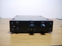
Just finished my Luxman M-120 "big brother" build. This is a project that will NEVER end as it is the "last stop" for auditioning my modular creations.
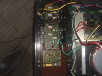
Picture #1 is the whole "dog" .. born a month ago and put through hell , even shorted out my yours truly...
Picture # 2 is what I hear , a modular Luxman/GX1 card , feeding a 8 output PB250 BJT - EF2 stage. power is conservative 200W /8R.. have seen actual 110V p/p on scope while in actual use. (police came soon after )
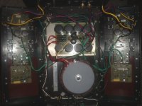
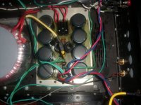
Picture # 3 is the new PS100 CLC power supply with 2 stage ground - 65,200 uF @ 100WV in place , replaced 20 year old Nichicon "bulging caps". Soundstage and headroom became MUCH better after this addition.
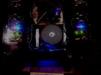
Picture # 4 is a night shot ... who says Xmas is in december. Really , blue and reds mean "do not touch" , amp is 1KVA/ + - 75V which can kill easily.
OS
Just finished my Luxman M-120 "big brother" build. This is a project that will NEVER end as it is the "last stop" for auditioning my modular creations.
Picture #1 is the whole "dog" .. born a month ago and put through hell , even shorted out my yours truly...
Picture # 2 is what I hear , a modular Luxman/GX1 card , feeding a 8 output PB250 BJT - EF2 stage. power is conservative 200W /8R.. have seen actual 110V p/p on scope while in actual use. (police came soon after
)Picture # 3 is the new PS100 CLC power supply with 2 stage ground - 65,200 uF @ 100WV in place , replaced 20 year old Nichicon "bulging caps". Soundstage and headroom became MUCH better after this addition.
Picture # 4 is a night shot ... who says Xmas is in december.
Really , blue and reds mean "do not touch" , amp is 1KVA/ + - 75V which can kill easily.OS
Attachments
Thanks for posting the circuit... always interesting to see.
I did some tests on non gfb amps, and the results were very surprising (really good) but I never developed it further.
I imagine your amp sounds very good... nice to see something different.
Hi there
I always likes amps with no feedback, or are my eyes not clear? why you have a higher voltage in the driver part? be carefull with that, only fets need + AND - 8 volts extra in the driver, bipolair not really.I like also the super emitter version vor a low ohms output and a high brake for the speaker, but with no feedback it wil always higher I have tubes as drivers no feedback dc coupled tot the mosfets, sounds very soundstage like with good speakers like fostex horn and tapped horn.
For better liniarity use ring emmiter transtitors in the power stage, for example sanken, maybe there are also lower power ring emmiters for driving, then you have something special and liniair even without feedback, it is a nice tryout.
looks nice I will test it later in multisim.
greetz
Last edited:
always likes amps with no feedback, or are my eyes not clear? why you have a higher voltage in the driver part? be carefull with that, only fets need + AND - 8 volts extra in the driver, bipolair not really.I like also the super emitter version vor a low ohms output and a high brake for the speaker, but with no feedback it wil always higher I have tubes as drivers no feedback dc coupled tot the mosfets, sounds very soundstage like with good speakers like fostex horn and tapped horn
Hi
a, Consider you home supply voltage will be down 5~10% some times ,so i take a higher.
b, choose a low emitter resistance can only supply higher current to drive sperker,but can't return the current to transistor circuit fou brake.
i don't know well as multisim but interest in the resouts if possble.
regard
- Home
- Amplifiers
- Solid State
- Post your Solid State pics here