I assume you have 2 transformers about 30-40 Watt. 2 x 1000uF ought to be enough.Not so many!
Just optimal!
25VA
2X1000μ are too low for a highend preamp!
Attachments

Le Monstre Photos and Thermal
Some phone photos of a Hiraga 8w Le Monstre after powering up!
Most people here are concerned with the high heat output here and I'm more concerned about the lack of heat! Just can't please everyone, huh!
Some phone photos of a Hiraga 8w Le Monstre after powering up!
Most people here are concerned with the high heat output here and I'm more concerned about the lack of heat! Just can't please everyone, huh!
An externally hosted image should be here but it was not working when we last tested it.
An externally hosted image should be here but it was not working when we last tested it.
An externally hosted image should be here but it was not working when we last tested it.
Thanks Andrew,Look at the loop area of your speaker leads. That big area will emit enormous emi.
I can't see any twisted pairs to help reduce susceptibility to emi.
Looks you have used a coaxial for the signal inputs. But big loop area at the terminations.
Yes a bit of tidying up to be done yet. I must say though, this is by far the quietest amp I have made yet, like put your ear into the driver at full output and there is only the very faintest tiny hiss. In fact when I turned it on first I thought "damn, no sound!" Anyway yes will adhere to best practice and tidy up connections!
When you mention twisted pairs, is that two single twisted wires from + output, I think I've seen this on other amps.
Many Thanks
https://www.youtube.com/watch?v=OTUj1z2cOFw&t=34s Powerful water-cooled repeater - https:/ From the experience - the best option for implementing a powerful repeater is a monoblock with flowing, water cooling. This construction allows us to obtain high power, dramatically simplifies the stabilization of regimes, reduces the weight and cost of the entire structure as a whole. Strictly speaking, the regimes remain unchanged, since the removal of thermal energy depends little on the environment and, in fact, thermostabilization can be ruled out. The rate of heat extraction (the heat sink temperature) is controlled by the flow rate. It is necessary to take into account that class "A" amplifiers require the use of a power source with a very low level of ripple. It is desirable to use stabilized food in the output stages of those working in class A. For example, the stabilizer, published in the journal RADIO number 12 for 2015. Parameters of the repeater on low-level signals, for a load of 4 Ohms at a resting current of 5 Amps. 1 W. - 0.0006%, 2.25 W.- 0.0012%, 6.25 W-0.0014, 12.25W -0.0017%, 25W-0.0022%, 42.25W. - 0.0025%. The interference at the output of the repeater was 0.4 millivolts. To reduce noise, the parallel connection of the BTT is used. The noise is reduced by N times, where the number of parallel connected BTTs. The noise of the power supply is reduced by such a repeater 45 times. It should be noted that the noise penetrating the output of the repeater from the power bars creates side components in the signal spectrum, worsen its linearity and dynamic range at small and ultra-small signal levels, since low-frequency components fall in the frequency band of interest. Obviously, the repeater has an enormous margin of linearity on the quietest signals and in detail processing the first WATT of the system. Pros - simplicity, good linearity. The quiescent current is equal to the current in the load. The repeater is not afraid of a long-term fault in the load !!! Complementary configuration provides a first-class version of the repeater with small non-linear distortions. The repeater has a high resolution and is able to transmit all the smallest overtones of the audio signal. The output signal contains significantly less than the higher harmonics and with a smaller amplitude. With all this, there is an additional intriguing moment associated with the decrease of even harmonics and the possibility to set the same balanced currents in each circuit individually, which further linearizes the output stage and eliminates the spread of the parameters of active elements in the repeater's arms. This construction of the output stage allows obtaining good linearity and using active elements without selection. The same balance currents are set automatically by the service system. Another important factor, the repeater has a zero input and output potential, a small input current, namely tenths of a milliampere, or when it does not go into AV mode, actually neutralizes even harmonics. The repeater operates with a quiescent current equal to the current in the load at maximum output power. Since the current mode of the output transistors is constant, respectively, the current transmission coefficient is constant. The repeater thus, in fact, operates at one point of its transfer characteristic. Accordingly, on a nonstationary signal, the current gain in the low-current and high-current regions of the repeater is constant. Hence, the correctness of the reproduction of envelopes is a formant. Due to the absence of the envelope deflection, the higher harmonics - the overtone of real musical instruments (having a level of millivolts) do not change during the passage through the repeater. Moreover, the high-frequency register of audio signals is not only the high-frequency signals themselves, but also primarily the harmonics of the mid-frequency spectrum. From the ensuing follows - different amplitudes of the input signal (one frequency), amplified with the same current gain. In addition, with the current unchanged, there are no temperature changes in semiconductors. Thus, there are no thermal distortions completely.
Below is description, forum and patents. Http://www.eapo.org/en/publications/bulletin/ea201410/html/1300368.html
Http://audioportal.hi-fi.ru/archive/index.php/t-51833.html
Https://www.youtube.com/watch?v=JK9jl-sgFgU http://eapatis.com/eaSearch/ms.exe?;EATXT|4|QL|NONEED$EA201300368A*%5CID https: // patentscope. Wipo.int/search/en/detail.jsf?docId=WO2014168518
Vladimir Fedosov/www.youtube.com/watch?v=OTUj1z2cOFw
A twisted pair carries one half of the signal from the source to the receiver on one wire. The return current flowing from receiver to source passes along the other wire. The electromagnetic fields created by those varying signal currents cancel each other because of the twisting of the two wires carrying current in opposite directions. It's the close coupling AND twisting of opposing currents that allows the cancelling of the emi fields (at a long distance compared to the twist pitch)..................
When you mention twisted pairs, is that two single twisted wires from + output, I think I've seen this on other amps.
Many Thanks
The emi can happen with line level signal currents and with speaker level signal currents and with pulsing PSU currents and mains wiring currents. Any current flowing around a circuit that VARIES creates an emi field.
Last edited:
Thanks again Andrew,A twisted pair carries one half of the signal from the source to the receiver on one wire. The return current flowing from receiver to source passes along the other wire. The electromagnetic fields created by those varying signal currents cancel each other because of the twisting of the two wires carrying current in opposite directions. It's the close coupling AND twisting of opposing currents that allows the cancelling of the emi fields (at a long distance compared to the twist pitch).
The emi can happen with line level signal currents and with speaker level signal currents and with pulsing PSU currents and mains wiring currents. Any current flowing around a circuit that VARIES creates an emi field.
Will be difficult to do this because the plus comes off the pcb while the minus is taken from the PS which is very close to the RCA output socket. Would a single shielded cable with the shield connected at the RCA socket to the same pin as the minus work instead of the twisted pair?
Thanks
That's a mistake that should be corrected.Thanks again Andrew,
Will be difficult to do this because the plus comes off the pcb while the minus is taken from the PS which is very close to the RCA output socket.
The speaker connection is a two wire connection. Those two wires should be close coupled along the whole route from Source to Receiver. For most of us that means a twisted pair from Amp OUT and Amp PG to the Spkr terminals.
The signal connection is a two wire connection. If you use a coaxial cable, then the core is Signal Hot/Flow and the screen/shield is the Signal Cold/Return. BOTH of these wires must be unbroken along the whole route from Source to Receiver.Would a single shielded cable with the shield connected at the RCA socket to the same pin as the minus work instead of the twisted pair?
Thanks
And the loop area at all the terminations should be kept as small as possible.
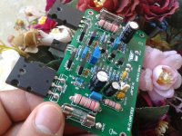
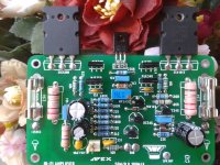
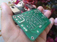
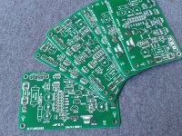
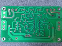
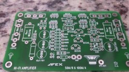
APEX AX11
Attachments
-
 18403942_1422258177833614_4250160250430605833_o.jpg360.9 KB · Views: 1,104
 -
 18404145_1057839154317738_3688640515266595599_o.jpg370.5 KB · Views: 1,067
 -
 18422156_1057839137651073_864652332834995525_o.jpg312.8 KB · Views: 1,009
 -
 18278855_1053262994775354_7200669519439224347_o.jpg539.5 KB · Views: 981
 -
 18320624_1053262761442044_5421346906676887887_o.jpg348.1 KB · Views: 945
 -
 18301194_1052955281472792_6716993907707917446_n.jpg76.5 KB · Views: 290
Last edited:
Very nice looking boards.APEX AX11
Are they available as a complete kit or just the PCB?
Thanks
Aubrey
Very nice looking boards.
Are they available as a complete kit or just the PCB?
Thanks
Aubrey
In this specific case, these boards were made by a brazilian pal, and there are none available.
Very nice looking boards.
Are they available as a complete kit or just the PCB?
Thanks
Aubrey
The plates were made for mi, I still only have 03 pairs of plates! Each pair costs US$ 7.50 + shipping
Sorry for my rude English.
Look at the loop area of your speaker leads. That big area will emit enormous emi.
I can't see any twisted pairs to help reduce susceptibility to emi.
Looks you have used a coaxial for the signal inputs. But big loop area at the terminations.
interesting theory, have you measured it and do you have data?
Nice job.
Yeah twisted pair won't be as effective as close coupling the cables to the chassis in reducing noise - twisted pair works best for differential signalling - the twists mean that both conductors get equally exposed to a noise source and so the noise stays as common mode and gets rejected and doesn't become differential noise. For an unbalanced system it helps to close-couple the cabling to the chassis or strap them to a well coupled earth conductor or bar - ie. bury your noise antenna in the ground so to speak...
Yeah twisted pair won't be as effective as close coupling the cables to the chassis in reducing noise - twisted pair works best for differential signalling - the twists mean that both conductors get equally exposed to a noise source and so the noise stays as common mode and gets rejected and doesn't become differential noise. For an unbalanced system it helps to close-couple the cabling to the chassis or strap them to a well coupled earth conductor or bar - ie. bury your noise antenna in the ground so to speak...
- Home
- Amplifiers
- Solid State
- Post your Solid State pics here