F5 Headamp
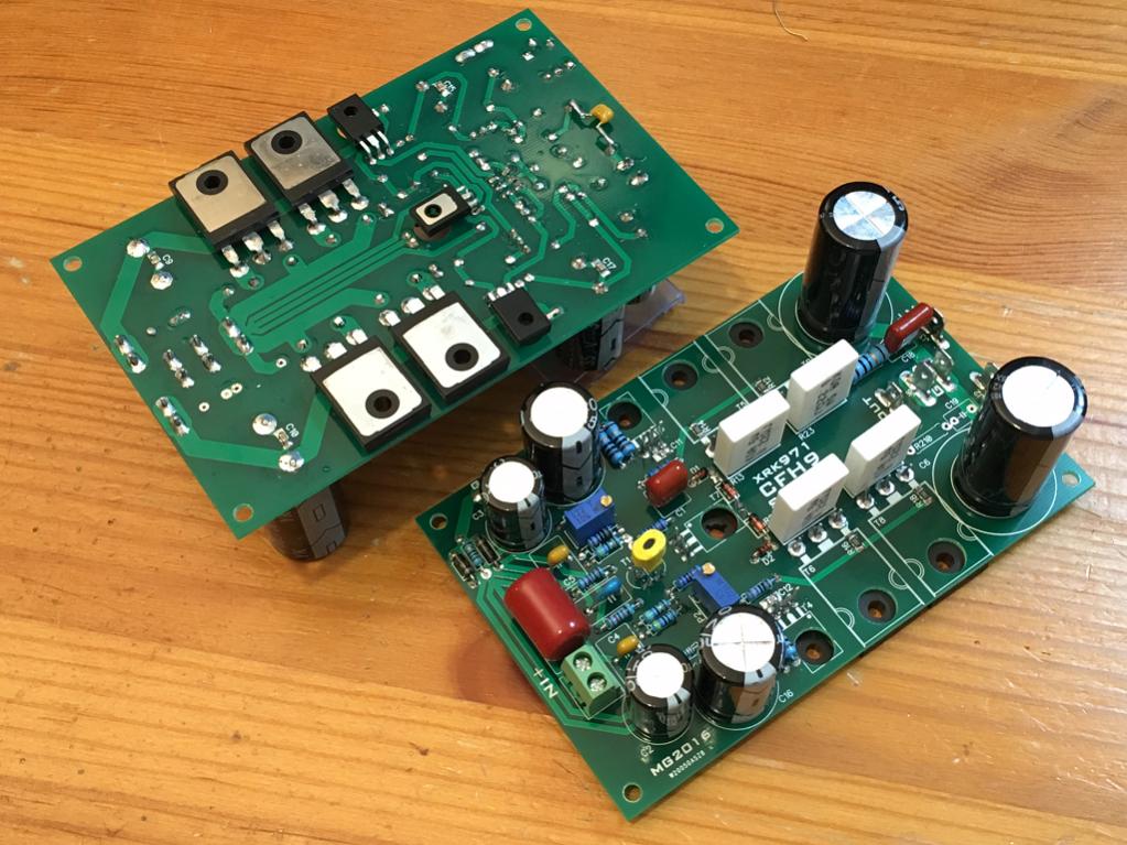
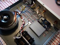
F5 Headamp. Using Prasi layout PCB.
http://www.diyaudio.com/forums/pass-labs/271926-f5-headamp-98.html#post4874463
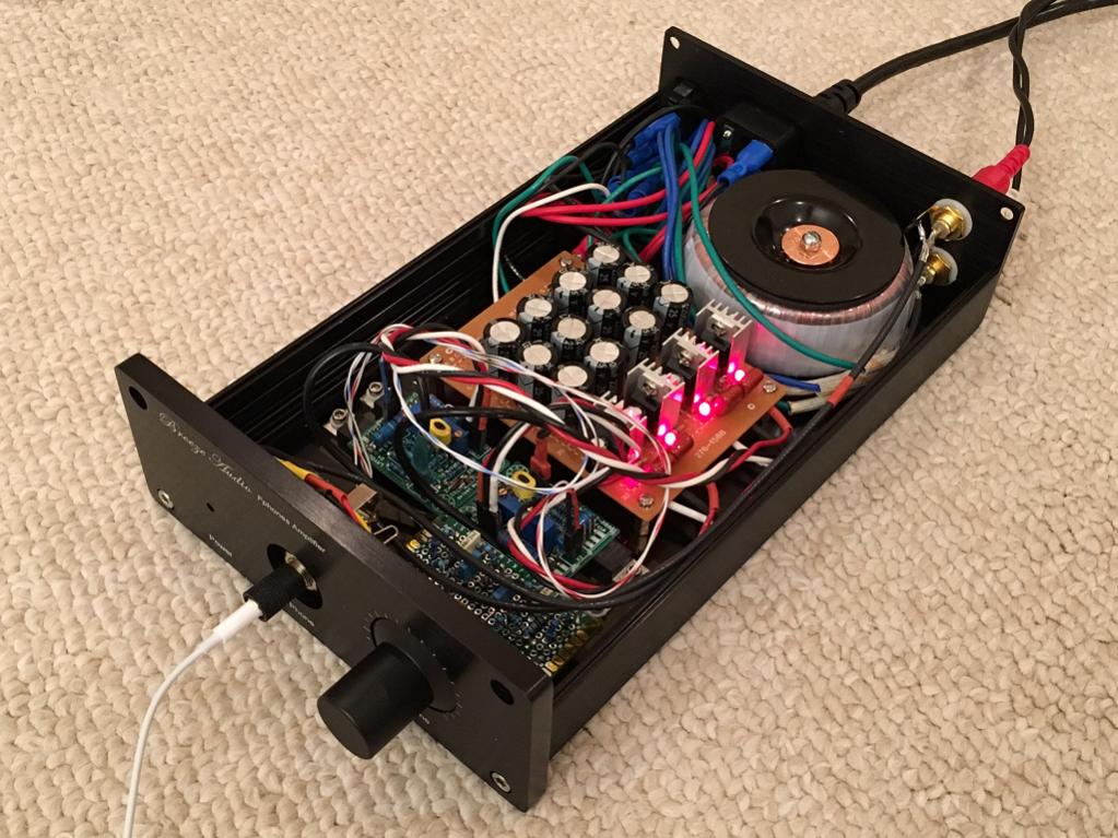
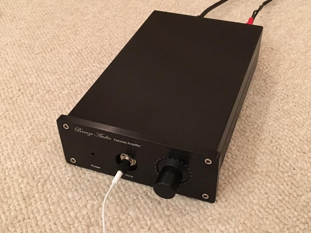
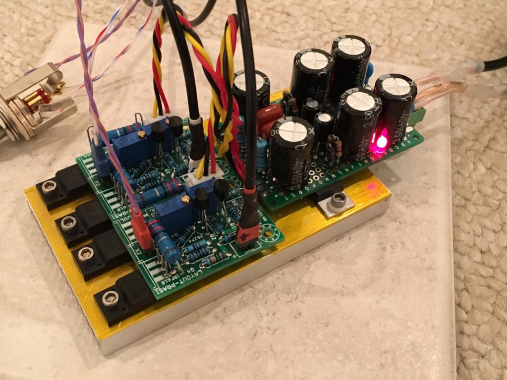
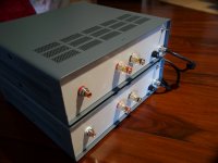
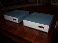
My first real aluminum case.
F5 Headamp. Using Prasi layout PCB.
http://www.diyaudio.com/forums/pass-labs/271926-f5-headamp-98.html#post4874463
My first real aluminum case.
really nice build, x . congrats!. could have tightly twisted all pairs or triplets of wires. whats the total build cost? about USD50-60 ?F5 Headamp. Using Prasi layout PCB.
http://www.diyaudio.com/forums/pass-labs/271926-f5-headamp-98.html#post4874463
My first real aluminum case.
reg
Prasi
really nice build, x . congrats!. could have tightly twisted all pairs or triplets of wires. whats the total build cost? about USD50-60 ?
reg
Prasi
Yes twisting outputs will increase crosstalk simple fact
Twisting rails even worst
Looks neat though but its wrong by all means
Twisting one output or input with one ground makes some sense
Twisting rails while keeping the ground out of the twist will also make some sense
Using triplets in parallel or triple twists is wrong by all means and its wrong to use in small signal far worst to hardwire transistor outputs
Kind regards
sakis
really nice build, x . congrats!. could have tightly twisted all pairs or triplets of wires. whats the total build cost? about USD50-60 ?
reg
Prasi
Case $40, trafo $17, amp $4, PSU $2, misc connectors $5. Maybe $70 or so.
Some just don't understand.
All current that comes out of a source MUST RETURN to that source. There are no exceptions.
For any current to flow from a source there must be a connection.
The return current also requires a connection.
Those connections make a TWO WIRE connection.
For least inductance those two wires must be at least close coupled. For better interference attenuation the close coupled wires can be twisted or coaxial.
there's the universal solution.
ALL connections should be twisted pair, or coaxial. The Two close coupled wires allow the current to Flow away from the Source and Return to the Source with least interference.
I twisted wires for sake of keeping the individual amp connections clear in my head: +/-15vdc supply, signal from cross feed filter/volume board, headphone output. There is already quite a bit of "crosstalk" at certain frequencies purposely added with crossfeed filter so I doubt that inadvertent "crosstalk" is an issue. I tried to keep AC wiring on back side of amp to prevent hum from being picked up. I was really worried about the RCA jacks being next to toroidal trafo with picking up hum from the mains but that was not an issue at all (I am using RG174 coax there). These little amp PCBs lack an on board smoothing cap of 1mF per rail, but so far it doesn't seem to be an issue. I will listen in comparison to my vero board version which has it and see if I can hear anything like bass dynamics missing. So far so good. Building a small case like this was very easy and fun. If you have a drill press it's quite easy. It's surprising how much heat the case walls can dissipate as a heatsink. It's absolutely not even warm. All those little headamp cases with fins are overkill.
Last edited:
Now to a dual polarity power supply.
An amplifier operating from dual polarity supplies draws current from one rail and returns that same current to the power supply via the other rail. If these currents are not exactly balanced then the residual current returns to source via the Power Ground back to the Zero Volts node of the PSU.
For the moment let's assume the residual current is zero because the two rails have exactly the same current draw.
When the amplifier sends some signal to the load, you will find that one supply rail current differs from the other supply rail current by the amount that flows to the load.
i.e. when the load current = X amperes, then
+ve rail current minus -ve rail current = X amperes.
The load returns it's current back to source. It returns that current via the wire to the Power Ground and thence to PSU Zero Volts.
The two supply rail currents are not equal when the load is passing some current.
Close coupling two currents that are not equal and opposite achieves none of the advantages that follow from the low inductance coupling.
One REQUIRES equal and opposite current flows for the close coupling interference minimising to occur.
The missing current is that which returns from the load. That third route MUST be close coupled to the two supply rails.
The TOTAL current in the triplet +ve supply, -ve supply and Power ground adds up to exactly zero. The total current in the triplet meets the close coupled requirement for equal and opposite current flow.
The dual polarity PSU requires it's three nodes to send and receive current along the close coupled triplet that couples to the loading stage.
Last edited:
I agree with AndrewT. I've measured and heard an improvement ever since I adopted this mindset during pcb layout and wiring.
No question about it. That's why twisted pair cables are faster and why they exist. It's not because it's nice. By twisting the wires, you end up with many tiny loops through which magnetic flux can go through (and in opposite directions). When you don't twist the wires, you essentially have a large surface area for the flux to penetrate. It's just physics.
The same applies for flux-generating conducting paths - by twisting these, you minimize flux density.
In all cases, I have had much better results with twisted wires. The only place where I get a bit confused is when it comes to wiring the input. Sure, twist the wires, but then which wires do you connect? The idea is to star the input grounds, so only 3 wires going to a stereo input, but I've found that this isn't effective. I ground each channel's input to each channel's ground. It seems to work better for me, then you can also twist the wires like koeksisters.
Last edited:
I think I did twist everything for signal and DC power but short toroidal trafo in/out wires not twisted. Is that what Andrews complaint is about?
My DC power is triplet twisted +15v/GND/-15v.
One area where I wasn't sure is whether or not to purposely connect the amp star ground point to earth ground? At this point earth ground is only connected to the case/chassis.
My DC power is triplet twisted +15v/GND/-15v.
One area where I wasn't sure is whether or not to purposely connect the amp star ground point to earth ground? At this point earth ground is only connected to the case/chassis.
Last edited:
I think I did twist everything for signal and DC power but short toroidal trafo in/out wires not twisted. Is that what Andrews complaint is about?
I think he's talking about the effective DC and transformer outputs.
As for the inputs, they do carry large voltages, but much lower currents, and magnetic field is proportional to current, so not as important. Still, no harm in twisting them. If you want to.
I make all my own interconnects amd speaker wires and none are shielded. The only place I have any shielded wire is from TT to MC preamp and MC preamp to phono pre. All my other interconnects, even from phono pre to preamp, are lose fine silver plated wire single wires or twisted wire.
As long as the wire is carrying about 1V there is no need for shielding. I even don't use shielded wire in amp or preamps I build and I'm 100% DIY across three complete systems.
As long as the wire is carrying about 1V there is no need for shielding. I even don't use shielded wire in amp or preamps I build and I'm 100% DIY across three complete systems.

Tripath T3 monoblocks
Just finished and only tested on small metal test speakers. No real idea how they sound except to say they work. Appears to be no hum or otherwise, always a good start. Even thought you buy the modules fully assembled build time is high. I spent most of the day just completing them after already spending a lot of hours on the back plate.
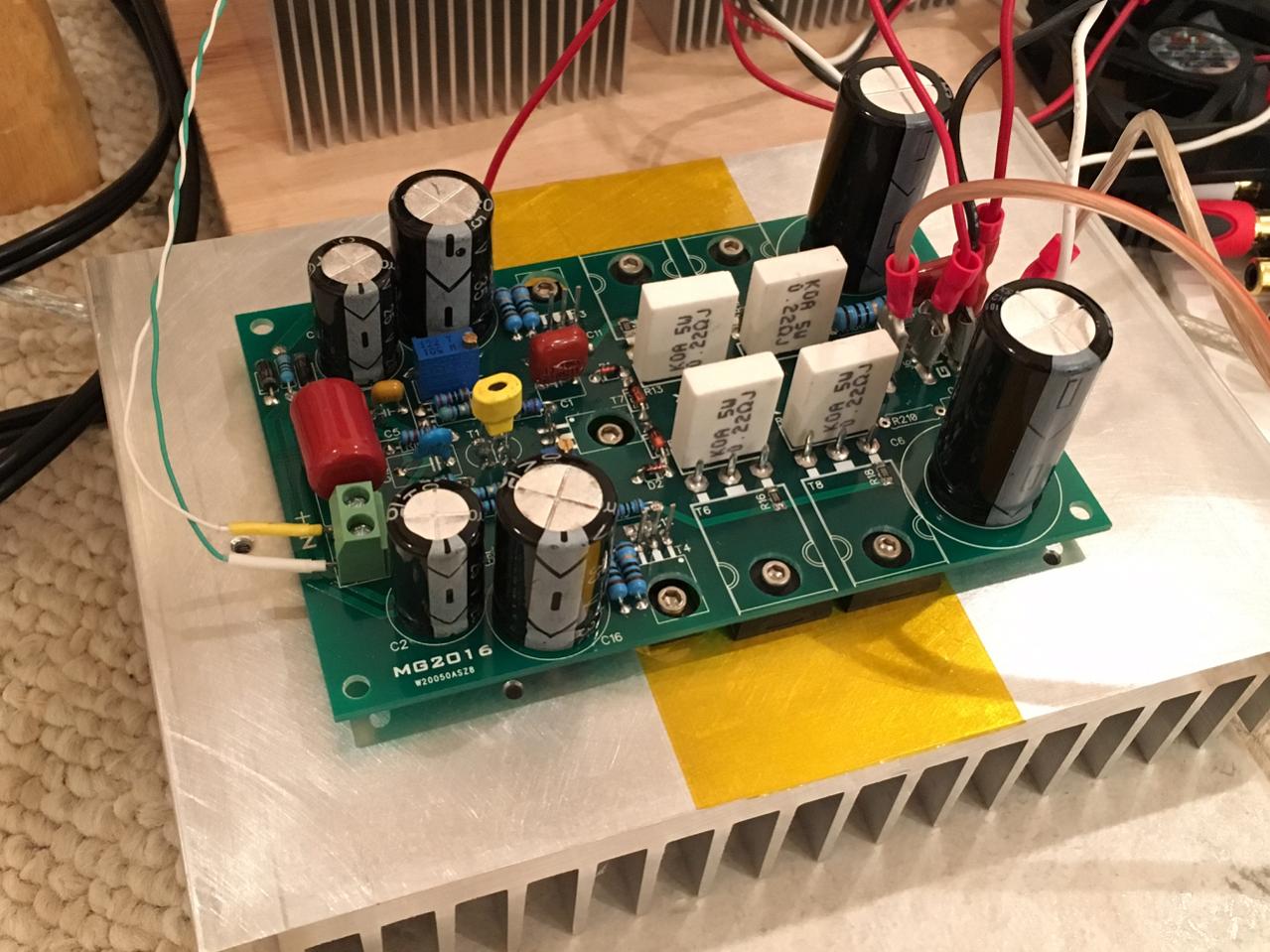
Bits and pieces; The Tripath modules are the T3 150W monoblocks. The gate controller chip proudly displays the Tripath name. The modules are quite small and cut down. No mechanical speaker protection, only small electro on board and not a lot of parts. Could be a sign of better things to come. The tranni is a 300VAC 30-0-30 and I paralleled the secondaries. That provides 30VAC @ 10A. Rectification is by a 10A rec. bridge which is soldered directly onto the first cap to ensure maximum current transfer to that cap. The secondaries are soldered directly to the rec, bridge. A 0.1uf poly bypasses the first cap to reduce bridge and cap noise.
The caps are 2X Mundorf MLytic 22,000uf 63V (44,000ud per monoblock). They are ultra low ESR audio grade and cost $60 each a total of four is required. I wanted to use the 47,000uf high current versions but I couldn't fit them in the case. Power wiring is via thick speaker wire and wiring to extra heavy duty speaker binding posts is very thick speaker wire and is quite short.
Connection to the board is by large brass spades so a board replacement is an easy job. RCAs are solid copper, palladium and Teflon. The enclosure is steel with a nice finish. Only four large screws hold the enclosure together as a lot of it "clicks" together. Speaker binding post are two way, are insulated and solid brass, big and heavy but nice!! The PS will deliver 420W and the amp can deliver 300W into 4ohms or 150W into 8ohm with 300W peaks. I called the monoblocks "Tutu" (think Mola Mola)
Just finished and only tested on small metal test speakers. No real idea how they sound except to say they work. Appears to be no hum or otherwise, always a good start. Even thought you buy the modules fully assembled build time is high. I spent most of the day just completing them after already spending a lot of hours on the back plate.
Bits and pieces; The Tripath modules are the T3 150W monoblocks. The gate controller chip proudly displays the Tripath name. The modules are quite small and cut down. No mechanical speaker protection, only small electro on board and not a lot of parts. Could be a sign of better things to come. The tranni is a 300VAC 30-0-30 and I paralleled the secondaries. That provides 30VAC @ 10A. Rectification is by a 10A rec. bridge which is soldered directly onto the first cap to ensure maximum current transfer to that cap. The secondaries are soldered directly to the rec, bridge. A 0.1uf poly bypasses the first cap to reduce bridge and cap noise.
The caps are 2X Mundorf MLytic 22,000uf 63V (44,000ud per monoblock). They are ultra low ESR audio grade and cost $60 each a total of four is required. I wanted to use the 47,000uf high current versions but I couldn't fit them in the case. Power wiring is via thick speaker wire and wiring to extra heavy duty speaker binding posts is very thick speaker wire and is quite short.
Connection to the board is by large brass spades so a board replacement is an easy job. RCAs are solid copper, palladium and Teflon. The enclosure is steel with a nice finish. Only four large screws hold the enclosure together as a lot of it "clicks" together. Speaker binding post are two way, are insulated and solid brass, big and heavy but nice!! The PS will deliver 420W and the amp can deliver 300W into 4ohms or 150W into 8ohm with 300W peaks. I called the monoblocks "Tutu" (think Mola Mola)
Attachments
- Home
- Amplifiers
- Solid State
- Post your Solid State pics here