Hi Thimios,
looks good, fine work.
Thanks my friend.
Thanks for all
")
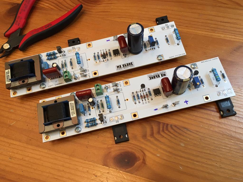
Finally I finished my amplifier
Based on LME49830 and 2sk1058 & 2sj162
Based on LME49830 and 2sk1058 & 2sj162
An externally hosted image should be here but it was not working when we last tested it.
An externally hosted image should be here but it was not working when we last tested it.
An externally hosted image should be here but it was not working when we last tested it.
An externally hosted image should be here but it was not working when we last tested it.
An externally hosted image should be here but it was not working when we last tested it.
An externally hosted image should be here but it was not working when we last tested it.
An externally hosted image should be here but it was not working when we last tested it.
An externally hosted image should be here but it was not working when we last tested it.
An externally hosted image should be here but it was not working when we last tested it.
An externally hosted image should be here but it was not working when we last tested it.
An externally hosted image should be here but it was not working when we last tested it.
Finally I finished my amplifier
Based on LME49830 and 2sk1058 & 2sj162
Can't see images
Looks great! Can you post a schematic for this amp?
CFH7 Amp
Amp description here:
http://www.diyaudio.com/forums/solid-state/294834-cfh7-amp.html
Sound clips here:
http://www.diyaudio.com/forums/soli...y-simple-quasi-mosfet-amp-14.html#post4811896
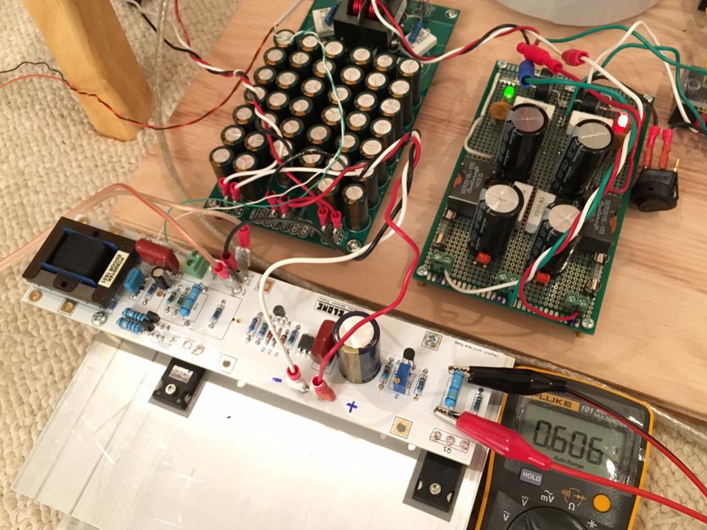
Running several days straight now, No fan needed, bias is stable at 160mA, offset stable within 5mV.

Amp description here:
http://www.diyaudio.com/forums/solid-state/294834-cfh7-amp.html
Sound clips here:
http://www.diyaudio.com/forums/soli...y-simple-quasi-mosfet-amp-14.html#post4811896
Running several days straight now, No fan needed, bias is stable at 160mA, offset stable within 5mV.
Attachments

Valery & Jeff zero distortion modular system
My first visit to this thread. I'm converted to this idea of PCB porn. Nice work and great photo.
Here is the schematicLooks great! Can you post a schematic for this amp?
Attachments

Member
Joined 2009
Paid Member
You could store it in "the cloud" (perhaps googledrive or onedrive) and publish the link...I've read the paper several times - it is very well written. My copy (pdf) exceeds the forum file size limit or I'd post it here.
Edwin

xrk971's questions and answers on 'Current Dumping' are now located here:
http://www.diyaudio.com/forums/solid-state/296530-wishing-learn-about-current-dumping.html


I think I will use CFP output stage next time, try to get 4W out of it
But to be fair, the 3,5W is plenty for all day listening, let me say 10W will do the job for sure.
sajti
The boards look very nice !!
The 3 pair one looks fully symetric 2x LTP + current mirror on top of it VFA ??
From my experiance it is very good to putt 47-100uF just by the drens/collectors to avoid ringing. Bellow my bad example how I have burned 20 pairs of mosfets while testing The fix was very easy, just a small cap by the each transistor. The last pic (Newfile 5) is the fixed one with 100uF by the drain + bootstrap.
But to be fair, the 3,5W is plenty for all day listening, let me say 10W will do the job for sure.
sajti
The boards look very nice !!
The 3 pair one looks fully symetric 2x LTP + current mirror on top of it VFA ??
From my experiance it is very good to putt 47-100uF just by the drens/collectors to avoid ringing. Bellow my bad example how I have burned 20 pairs of mosfets while testing
The fix was very easy, just a small cap by the each transistor. The last pic (Newfile 5) is the fixed one with 100uF by the drain + bootstrap.Attachments


Last edited:
- Home
- Amplifiers
- Solid State
- Post your Solid State pics here