smithy is a big craftsmen
Smithy, you are a big craftsman!!
You will understand the heaviness of my statement after a couple of days, when i will post my complette project. To the present, i am in process of constructing the pannels of my project.
Again, your work on this project may be the deffinition of term DO IT YOUR SELF.
My compliments and my friendship to you!
Fotios
Re: smithy is a big craftsmen
Thank you Fotios for your kind words! I am indeed looking forward to seeing your completed project, as what I have seen so far looks great. And as I said before, being able to actually see what others have done gives ideas and inspiration for the next project. So much to learn, so little time...
fotios said:Smithy, you are a big craftsman!!
You will understand the heaviness of my statement after a couple of days, when i will post my complette project. To the present, i am in process of constructing the pannels of my project.
Again, your work on this project may be the deffinition of term DO IT YOUR SELF.
My compliments and my friendship to you!
Fotios
Thank you Fotios for your kind words! I am indeed looking forward to seeing your completed project, as what I have seen so far looks great. And as I said before, being able to actually see what others have done gives ideas and inspiration for the next project. So much to learn, so little time...
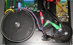
smithy666 said:And the last one showing the transformer/caps again and the Borbely speaker protection (DC detect/delay on)
So your not using Aussie Amps PSU? How do you have it wired up then? Do you have a diagram?
What kind of fuses are you using between the caps and amp module?
And what is the black connector the blue and red cables are connecting into and then leading to the caps? (http://www.diyaudio.com/forums/attachment.php?s=&postid=1578960&stamp=1218018572)
soundengine355 said:
So your not using Aussie Amps PSU? How do you have it wired up then? Do you have a diagram?
No I'm not using their PSU. The wiring is a pretty standard amp PS configuration - the transformer has 2 x 45V/200VA per winding taps (+ 2x12V for the speaker protector). The two 45V taps are wired in series, forming a 45-0-45 configuration with the centre (joined) wire connecting to the 0V of the Mundorf caps (the mundorf caps are wired in series +:- joined +:-, with the join being 0V). The 45/45 leads connect to the bridge and the +/- of the bridge connects to the +/- of the caps. The +/- from the caps (which are now about +/-67V without load) are connected to the amp modules +ve, -ve via 5A fuses mounted on the sub panel. The 0V from the caps is connected to the amp module's 0V (PS GND). Mains earth is also connected to the gnd on the amp module.
The "black connector" is the IXYS bridge rectifier mounted on the sub panel.
That's it! Sorry if it is not clear - following the wiring on the photos should help. I can quickly whip up a schematic if it helps
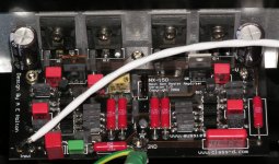
smithy666 said:This is my softstart board (see another thread if anyone wants PCBs)
Nice job - pretty neat!

Could you please point me to the thread about your softstart?
Thanks!
Here is the link:
http://www.diyaudio.com/forums/showthread.php?threadid=98879
http://www.diyaudio.com/forums/showthread.php?threadid=98879
Hi!
Where is the schematic of Soft-Start circuit & the rest?
Regards zeoN_Rider
smithy666 said:
Where is the schematic of Soft-Start circuit & the rest?
Regards zeoN_Rider
Re: Hi!
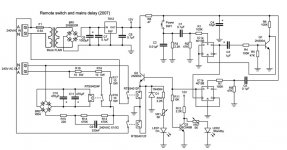
Here is the softstart/remote switch schematic
zeonrider said:
Where is the schematic of Soft-Start circuit & the rest?
Regards zeoN_Rider
Here is the softstart/remote switch schematic
Attachments
Re: Re: Hi!
smithy666 said:
Here is the softstart/remote switch schematic [/\
QUOTE]
Thanks!
Regards zeoN_Rider
nxv500
Hi Guys
Here is my latest creation for those that are interested.
310 Watts RMS continuous sine wave into 8 Ohms
550 Watts RMS continuous sine wave into 4 Ohms
860 Watts RMS continuous sine wave into 2 Ohms
Hi Guys
Here is my latest creation for those that are interested.
An externally hosted image should be here but it was not working when we last tested it.
310 Watts RMS continuous sine wave into 8 Ohms
550 Watts RMS continuous sine wave into 4 Ohms
860 Watts RMS continuous sine wave into 2 Ohms
YUP FOTIOS THIS IS MY EMAIL AD ejtsoundsystem@yahoo.com
thank you. i hope you sent it...
thank you. i hope you sent it...


Yes
I can only agree with Hugh.
(it is not because he is an aussie, too, that he like tony's work)
 And it is not the first time I see some 'perfect' pcb amplifier stuff from Mr Holton.
May I add also, that Hugh 'AKSA' Dean makes them 'perfectly designed' PCB layouts him self.
He once got one top class review from Fred Dickmann!!!!
And there are not many that Fred would praise, unless they really deserve this
AuussieAmplifier: http://www.aussieamplifiers.com/
AKSA Amplifiers & PCB Kits:
Aspen Amplifiers = AKSA
Lineup
I can only agree with Hugh.
(it is not because he is an aussie, too, that he like tony's work)
And it is not the first time I see some 'perfect' pcb amplifier stuff from Mr Holton.May I add also, that Hugh 'AKSA' Dean makes them 'perfectly designed' PCB layouts him self.
He once got one top class review from Fred Dickmann!!!!
And there are not many that Fred would praise, unless they really deserve this
AuussieAmplifier: http://www.aussieamplifiers.com/
An externally hosted image should be here but it was not working when we last tested it.
AKSA Amplifiers & PCB Kits:
Aspen Amplifiers = AKSA
Lineup
- Home
- Amplifiers
- Solid State
- Post your Solid State pics here