ejtsoundsystem said:CAN YOU SHARED THE SCHEMATIC DIAGRAM FOR THAT AMP???
Please, not in common view.
The reasons are:
1) I don't like the appearance of some people here, who looks like the two old mans Statler & Waldorf on the balcony of Muppet Show to criticize for kidding - after they have drink enough beers - ( DO YOU HEAR Mr. MODERATOR??? ).
2) There is in my country enough electronics who many times they copied my plans to make money with succes.
3) I make this job for living - not for hobby.
4) My plans are not so much exceptional, the only that i make well it is the correct pcb drawings and the use of first quality parts.
So, to facilitate you, please send me e-mails with your link to post you the plans privately.
Fotios
Here is my build of NCC 200 amplifiers
http://i259.photobucket.com/albums/hh290/337alant/ncc2002.jpg
http://i259.photobucket.com/albums/hh290/337alant/ncc2003.jpg
http://i259.photobucket.com/albums/hh290/337alant/ncc2001.jpg
I am building another amp case as well thats what the second transformer is for
Alan
http://i259.photobucket.com/albums/hh290/337alant/ncc2002.jpg
http://i259.photobucket.com/albums/hh290/337alant/ncc2003.jpg
http://i259.photobucket.com/albums/hh290/337alant/ncc2001.jpg
I am building another amp case as well thats what the second transformer is for
Alan
337alant said:Here is my build of NCC 200 amplifiers
http://i259.photobucket.com/albums/hh290/337alant/ncc2002.jpg
http://i259.photobucket.com/albums/hh290/337alant/ncc2003.jpg
http://i259.photobucket.com/albums/hh290/337alant/ncc2001.jpg
I am building another amp case as well thats what the second transformer is for
Alan
My compliments sir!
First class hardwork. Nice cases. From where they have find you?
Fotios
fotios said:
Please, not in common view.
The reasons are:
1) I don't like the appearance of some people here, who looks like the two old mans Statler & Waldorf on the balcony of Muppet Show to criticize for kidding - after they have drink enough beers - ( DO YOU HEAR Mr. MODERATOR??? ).
2) There is in my country enough electronics who many times they copied my plans to make money with succes.
3) I make this job for living - not for hobby.
4) My plans are not so much exceptional, the only that i make well it is the correct pcb drawings and the use of first quality parts.
So, to facilitate you, please send me e-mails with your link to post you the plans privately.
Fotios
I know what you mean .. fotios.
Some can not even say: Thanks
")
when I publish my job from a circuit design & post it here
Very bad
Bad people ???Re: Re: Yap
I've been lately extremely busy with my dayjob - I'm afraid I have to delay publishing the new amp on my web site.
Here's a quick snapshot of the YAP amp pulse response in a capacitive load.
- 10Vpp 500KHz pulse.
- 4ohm || 100nF load.
- Zoebel network is in place: 10ohm+100nF
- 0.6uH (damped by 4.7ohm) output coil.
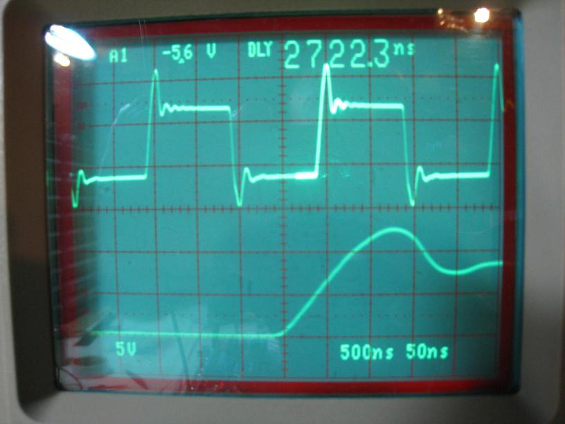
Upper trace is real time, lower trace is delayed sweep (magnified trailing edge).
Nice amp (yours) BTW. If I would have the same talent, pacience and time to lay out PCBs as yourself I could probably save a little fortune in PCB costs.
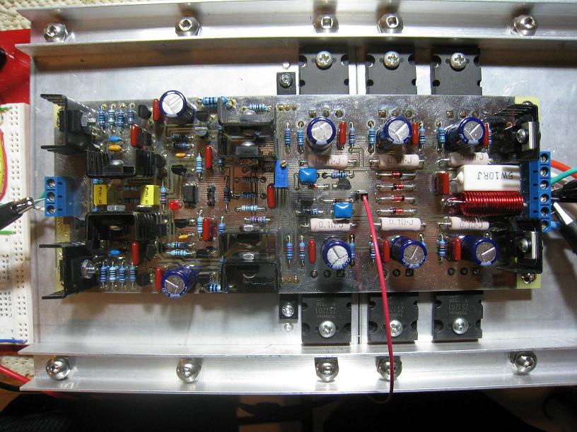
A better photo of the finished OPS:
fotios said:
Also if it is easy, an indicating photo from your scope screen?
I've been lately extremely busy with my dayjob - I'm afraid I have to delay publishing the new amp on my web site.
Here's a quick snapshot of the YAP amp pulse response in a capacitive load.
- 10Vpp 500KHz pulse.
- 4ohm || 100nF load.
- Zoebel network is in place: 10ohm+100nF
- 0.6uH (damped by 4.7ohm) output coil.
Upper trace is real time, lower trace is delayed sweep (magnified trailing edge).
Nice amp (yours) BTW. If I would have the same talent, pacience and time to lay out PCBs as yourself I could probably save a little fortune in PCB costs.
A better photo of the finished OPS:
Hello all, this is my piece. Originally designed DPA330 by Pavel Dudek, big thanks to him. My construction:
An externally hosted image should be here but it was not working when we last tested it.
Re: Re: Re: Yap
syn08
Your YAP is a very good amplifier .. and you know it
stephunk
Pavel Dudek has made some really good amplifiers.
I am sure your amp is playing some very good music.
syn08 said:I've been lately extremely busy with my dayjob - I'm afraid I have to delay publishing the new amp on my web site.
- 10Vpp 500KHz pulse.
- 4ohm || 100nF load.
- Zoebel network is in place: 10ohm+100nF
- 0.6uH (damped by 4.7ohm) output coil.
stephunk said:Hello all, this is my piece.
Originally designed DPA330 by Pavel Dudek, big thanks to him.
syn08
Your YAP is a very good amplifier .. and you know it
stephunk
Pavel Dudek has made some really good amplifiers.
I am sure your amp is playing some very good music.
Thanks lineup. This topology has really good performance. By reading this thread, I see many superior constructions, little bit shamy about mine 
Here´s a better wiew for you.
have a nice day
Here´s a better wiew for you.
An externally hosted image should be here but it was not working when we last tested it.
have a nice day

Dudaindc, not exactly, protection circuitry still missing. But soon will be completed, also front panel is completed and waits for assembly.
Syn 08-well done, very nice PCB. Amp looks to be stable. 2 Months ago, i tried the Alexander amp construction. Now i´m working on PCB, because original PCB looks awful, separated output stage etc..my prototype board worked very good, afer some little changes(-3dB at approx 700kHz in 6.6Ohm). I want to use it for driving the tweeters on my 2way system(nowdays completing).
Changes: in output stage the IR fets were used, Ne5532 on input. Also protection circuitry was added. Whole thing will be placed on single PCB-i hate cables..If the day had 25hours at least
greetings
337alant said:My compliments sir!
First class hardwork. Nice cases. From where they have find you?
Thank you, the cases are from Modu in italy
Amplifer boards from Avondale Audio
Your work is also excellent
Alan
Many thanks Alan for the link!
Nice cases in very logical price! And first of all from a country near all of us the Europeans.
To all: follow this link:
http://www.modu.it
Fotios
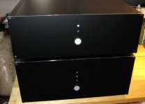
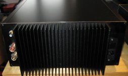
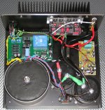
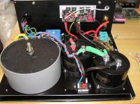
And the rear of the NX150. Conrad heatsink, WBT RCA and binding posts. The cases had to fit a particular size (non standard), so I was limited as to what cases were available. In the end I designed them using Front Panel Express' software.
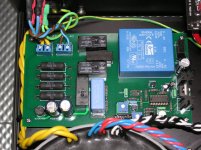
Inside the amp case (as per photo on previous page) is 1 x Aussie Amplifiers NX150 module, custom 400VA potted toroid, 2 x Mundorf 47000uF/80V caps, Borbely speaker protector and my own soft start/switch on board. Now to finish the 23W subwoofer...
Inside the amp case (as per photo on previous page) is 1 x Aussie Amplifiers NX150 module, custom 400VA potted toroid, 2 x Mundorf 47000uF/80V caps, Borbely speaker protector and my own soft start/switch on board. Now to finish the 23W subwoofer...
Attachments
smithy666 said:And the rear of the NX150. Conrad heatsink, WBT RCA and binding posts. The cases had to fit a particular size (non standard), so I was limited as to what cases were available. In the end I designed them using Front Panel Express' software.
Inside the amp case (as per photo on previous page) is 1 x Aussie Amplifiers NX150 module, custom 400VA potted toroid, 2 x Mundorf 47000uF/80V caps, Borbely speaker protector and my own soft start/switch on board. Now to finish the 23W subwoofer...
Hi,
Do you have a picture of the inside? How did you fit the Mundorf 47000uF/80V caps? to the PSU? or to the amplifier module?
soundengine355 said:
Hi,
Do you have a picture of the inside? How did you fit the Mundorf 47000uF/80V caps? to the PSU? or to the amplifier module?
Here is a pic of the inside (top view) showing the transformer, caps etc. I designed the case to have a sub-panel. All the electronics mounted on this and this subpanel was then bolted to the bottom panel with 9 standoffs.
Attachments
- Home
- Amplifiers
- Solid State
- Post your Solid State pics here