It seams they are familiar to me .....BTW very good sounding amplifier .
Regards,Alex
Credits Alex MM and Mr. Mile.
best regards
Attachments
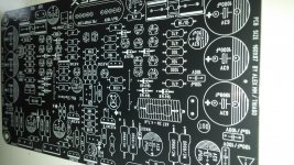
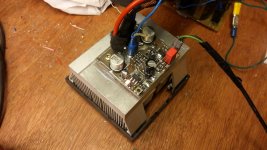
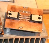
Simple amplifier design by me
Heatsink is undersize but only for testing.
Some of my friends built it and they like it verry much.
emprit bravo....
New LM1875 on the block
It has been a very productive period over here. Hereby I would like to show my humble new build . It is based onto the LM1875 which allows for a relatively compact build. It is 5.3 cm (H) x 16 cm (W) x 16 cm (D) in size and produces about 2 x 18 Watts RMS.
It is so small in height that the original transformer and mount plates did not fit into the cabinet without making a shorted turn (mounting bolt touching both sides of the cabinet). Instead of isolating the bolt I decided to pot the center of the transformer by using (heat resistant) epoxy resin. This is not only nicer for mounting the transformer but could also help in reducing mechanical hum (although Amplimo is very good in tackling this phenomenon):
In addition I made a dedicated PCB for the VU meters including a PSU for the low voltage circuits:
Later I added a little soldereable fuse so that this circuit is fused separately.
I added a metal strip just behind the VU meter which has 3 functions e.g. it keeps the VU meter firmly attached, it harbours a voltage regulator and it allows for a nice space for attaching the LEDs:
The amplifier PCB with the PSU:
The amplifier has an excellent square wave response, showing no signs of ringing even at several kHz:
The final result:
All brass stand offs are tapered into the cabinet, screws are countersunk:
Here the exta miniature fuse is visible onto the low voltage board, next to the block transformer.
I hope you all like the amplifier. As a bonus, hereby a YouTube video of the amplifier :
https://www.youtube.com/watch?v=9nsOUTo_ZYY
It has been a very productive period over here
. Hereby I would like to show my humble new build . It is based onto the LM1875 which allows for a relatively compact build. It is 5.3 cm (H) x 16 cm (W) x 16 cm (D) in size and produces about 2 x 18 Watts RMS. It is so small in height that the original transformer and mount plates did not fit into the cabinet without making a shorted turn (mounting bolt touching both sides of the cabinet). Instead of isolating the bolt I decided to pot the center of the transformer by using (heat resistant) epoxy resin. This is not only nicer for mounting the transformer but could also help in reducing mechanical hum (although Amplimo is very good in tackling this phenomenon):
An externally hosted image should be here but it was not working when we last tested it.
In addition I made a dedicated PCB for the VU meters including a PSU for the low voltage circuits:
An externally hosted image should be here but it was not working when we last tested it.
Later I added a little soldereable fuse so that this circuit is fused separately.
I added a metal strip just behind the VU meter which has 3 functions e.g. it keeps the VU meter firmly attached, it harbours a voltage regulator and it allows for a nice space for attaching the LEDs:
An externally hosted image should be here but it was not working when we last tested it.
The amplifier PCB with the PSU:
An externally hosted image should be here but it was not working when we last tested it.
The amplifier has an excellent square wave response, showing no signs of ringing even at several kHz:
An externally hosted image should be here but it was not working when we last tested it.
The final result:
An externally hosted image should be here but it was not working when we last tested it.
An externally hosted image should be here but it was not working when we last tested it.
An externally hosted image should be here but it was not working when we last tested it.
An externally hosted image should be here but it was not working when we last tested it.
All brass stand offs are tapered into the cabinet, screws are countersunk:
An externally hosted image should be here but it was not working when we last tested it.
An externally hosted image should be here but it was not working when we last tested it.
Here the exta miniature fuse is visible onto the low voltage board, next to the block transformer.
An externally hosted image should be here but it was not working when we last tested it.
An externally hosted image should be here but it was not working when we last tested it.
An externally hosted image should be here but it was not working when we last tested it.
I hope you all like the amplifier
. As a bonus, hereby a YouTube video of the amplifier :https://www.youtube.com/watch?v=9nsOUTo_ZYY
Thanks guys !
For cutting I use a Bahco 301 coping saw. This case in particular is very easy to cut because the front is made of (polyactic acid) plastic:
However, I also used this method to cut through 6mm thick aluminium which also goes very smootly. However, I would then advice to add some cutting oil to the saw blade. It will then last longer, the saw is less likely to clogg up and cutting will go much more smoothly due to less friction.
I carefully measure and draw the lines, which I always draw a fraction smaller than it should be. This way I have some material left to be still able to file the surface very smooth afterwards.
Then I drill 6 holes by making use of a drill press; four at the corners and two in the middle. Then I carefully saw wile following the line very meticulous. Sometimes I use a metal piece as a saw guide for convenience. Afterwards I file and sand the kerf smooth. It gives a very statisfying result, which is much cheaper than fancy methods such as laser cutting, but when excecuted well, could be still very accurate.
! For cutting I use a Bahco 301 coping saw. This case in particular is very easy to cut because the front is made of (polyactic acid) plastic:
An externally hosted image should be here but it was not working when we last tested it.
However, I also used this method to cut through 6mm thick aluminium which also goes very smootly. However, I would then advice to add some cutting oil to the saw blade. It will then last longer, the saw is less likely to clogg up and cutting will go much more smoothly due to less friction.
I carefully measure and draw the lines, which I always draw a fraction smaller than it should be. This way I have some material left to be still able to file the surface very smooth afterwards.
An externally hosted image should be here but it was not working when we last tested it.
Then I drill 6 holes by making use of a drill press; four at the corners and two in the middle. Then I carefully saw wile following the line very meticulous. Sometimes I use a metal piece as a saw guide for convenience. Afterwards I file and sand the kerf smooth. It gives a very statisfying result, which is much cheaper than fancy methods such as laser cutting, but when excecuted well, could be still very accurate
.I always have problems with making edges straight and angles right (with a file)...
Especially corners - they never look right.
Just because of this I avoid rectangular vu meters, and install round ones
Clamp a couple straight edges to the piece you are filing. If you're filing plastic, the file will stop cutting when it runs into steel.
Maybe you could try to use a guide, for example a piece of straight metal which you clamp next to the kerf and then file very meticulous till you reach the guide. A mistake is easily made when filing. Therefore I always file very slowly and check regularely by comparing the object with the hole. I have bought a set of Bahco files for this. For the corners I use a square file, while for the flat side I use a rectangular file. When I need to file a lot I start with using the 'flat bastard' file, followed by the 'flat smooth' file. However, I don't need the flat bastard much, mostly flat smooth is sufficient and no large areas need to be filed straight. Good files are pretty expensive but I have to say, they are worth their money in gold. And they seem to last forever .
.MiniCFP
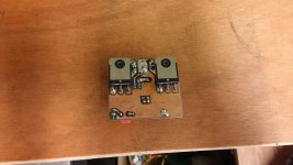
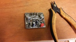
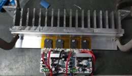
The smallest amp I have ever made
Only a few semiconductors in audio path. Current feedback, CFP input pair, simple VAS stage + latFET output. For now supplied +/-44V drives 4R load very nice. Dominant second harmonic, very smooth top end. Need only a spare time to upgrade the board a bit.
The smallest amp I have ever made
Only a few semiconductors in audio path. Current feedback, CFP input pair, simple VAS stage + latFET output. For now supplied +/-44V drives 4R load very nice. Dominant second harmonic, very smooth top end. Need only a spare time to upgrade the board a bit.
Attachments
Nice!MiniCFP
The smallest amp I have ever made
Only a few semiconductors in audio path. Current feedback, CFP input pair, simple VAS stage + latFET output. For now supplied +/-44V drives 4R load very nice. Dominant second harmonic, very smooth top end. Need only a spare time to upgrade the board a bit.
Give to us some of your toys
Member
Joined 2009
Paid Member
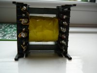
SMPS trafo
125Khz ETD34 400/800W half-bridge 60-0-60V from 240VAC input transformer with aux winding for control and 15-0-15V aux output winding. Constructed using TIW wire to avoid creepage and clearance problems and REDUCE leakage inductance, most windings are home made Litz. Presently under test and working ok, yes the fill fector could be higher but in a prototype better to have underfill than overfill.
125Khz ETD34 400/800W half-bridge 60-0-60V from 240VAC input transformer with aux winding for control and 15-0-15V aux output winding. Constructed using TIW wire to avoid creepage and clearance problems and REDUCE leakage inductance, most windings are home made Litz. Presently under test and working ok, yes the fill fector could be higher but in a prototype better to have underfill than overfill.
Attachments
.JPG)
.JPG)
.JPG)
.JPG)
- Home
- Amplifiers
- Solid State
- Post your Solid State pics here