Venar
Very nice and different style.
What are your temp readings top and bottom of the sink, or more importantly, the temps at the area where your outputs bolt to the heat sink?
This kind of configuration makes it difficult to get an even temp on all output devices if your running a high bias?
Regards
David
thanks awverk
amp hasn't powered up yet
but
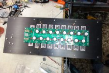
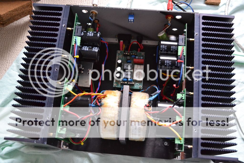
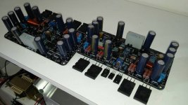
thermal consideration took in mind when designing
as you can see output devices are spread as far away as possible between them,and asymmetrically to the heatsink(more near to the bottom as the heat spreading to the top and the output air is colder at the bottom of the heatsink
mosfets will rapidly dissipate heat thanks to keratherm reds
so I think that thermal difference between top and bottom will be minimal
and yes bias is high( first 25W@class A operation)
amp hasn't powered up yet
but
thermal consideration took in mind when designing
as you can see output devices are spread as far away as possible between them,and asymmetrically to the heatsink(more near to the bottom as the heat spreading to the top and the output air is colder at the bottom of the heatsink
mosfets will rapidly dissipate heat thanks to keratherm reds
so I think that thermal difference between top and bottom will be minimal
and yes bias is high( first 25W@class A operation)
Last edited:
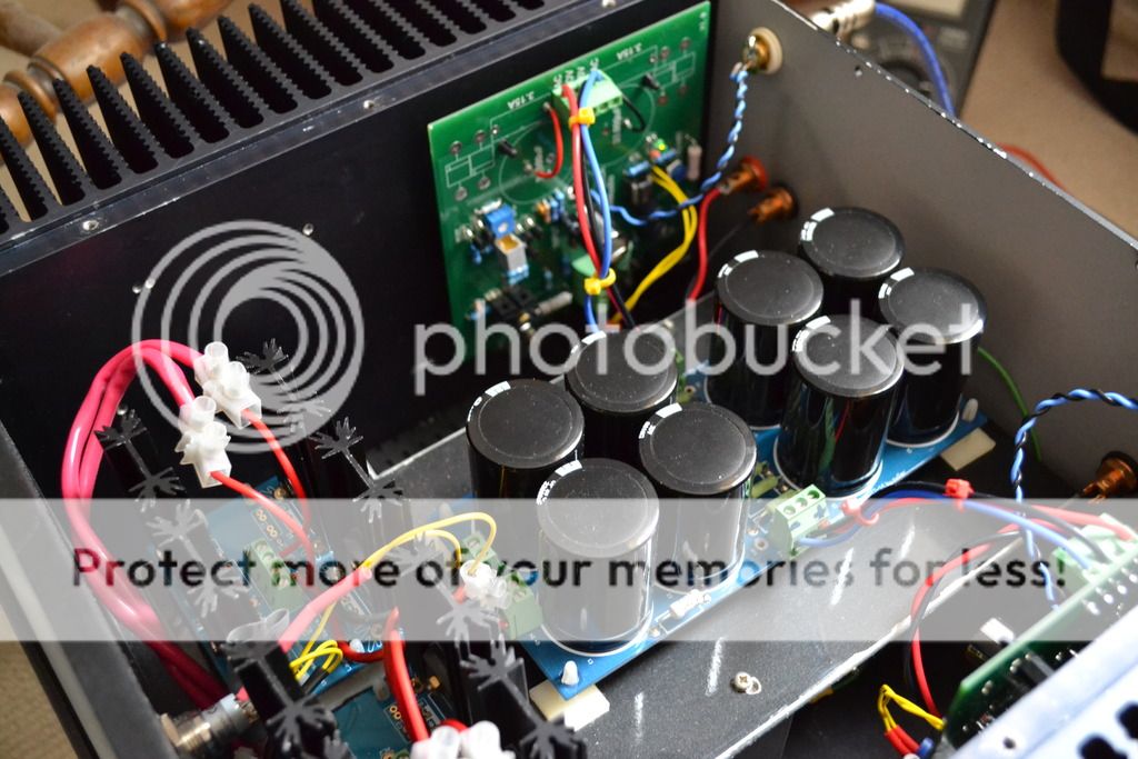
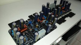
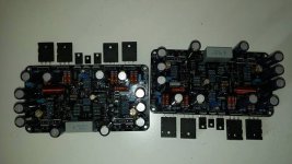
A few pics of my most recent build which is a Colin J Wonfor(Incatech; Magnum;Tellurium Q designer) little class A amp the sound quality of which I am blown away by. The amp was first built with the basic amp board and a single supply for both channels before going dual mono and adding in the regulated tracking power supply which made a very worthwhile lift in sound.This is single ended class A amp which outputs about 14 watts but sounds far more powerful.
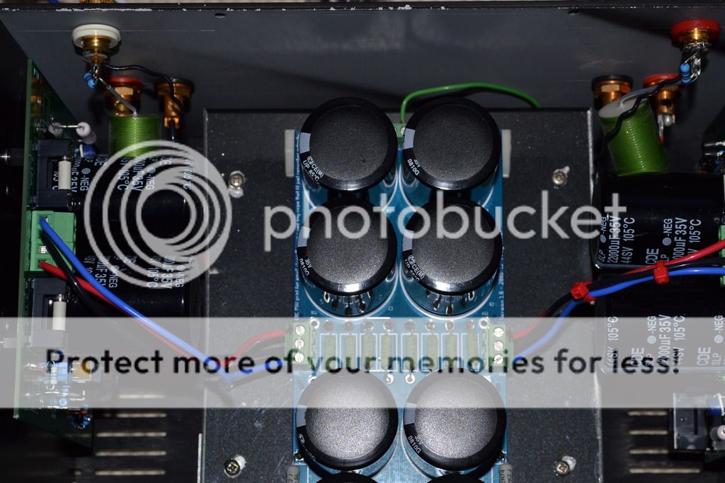
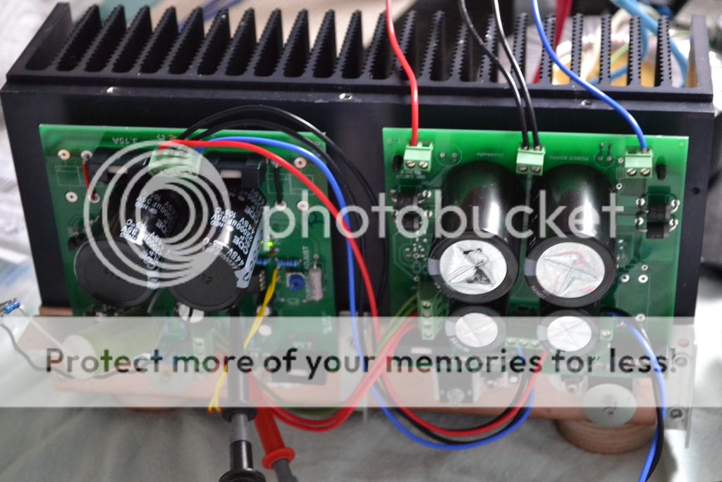
And with the tracking p/s.


And with the tracking p/s.


Last edited:
Wow Marra, nice work! It looks great ") .
.
I have just finished headamp number 12. Since I have already so many, this one should be very compact . I bought the unpopulated PCB from Michiel Stegeman at forum.zelfbouwaudio.com (the Dutch equivalent of Diyaudio). Al the SMD parts are soldered with just a regular soldering iron. The complete amplifier is about 9.5 cm (W) x 4 cm (H) x 16 cm (D) in size.
.I have just finished headamp number 12
. Since I have already so many, this one should be very compact . I bought the unpopulated PCB from Michiel Stegeman at forum.zelfbouwaudio.com (the Dutch equivalent of Diyaudio). Al the SMD parts are soldered with just a regular soldering iron. The complete amplifier is about 9.5 cm (W) x 4 cm (H) x 16 cm (D) in size. An externally hosted image should be here but it was not working when we last tested it.
An externally hosted image should be here but it was not working when we last tested it.
An externally hosted image should be here but it was not working when we last tested it.
An externally hosted image should be here but it was not working when we last tested it.
An externally hosted image should be here but it was not working when we last tested it.
An externally hosted image should be here but it was not working when we last tested it.
An externally hosted image should be here but it was not working when we last tested it.
Michael - Another very nice looking build. Can we see the inside?
Rick
Thanks Rick! Of course
I changed the amplifier today a little bit. At first I implemented a little soldereable fuse internally just before the power switch. However, I thought a fuse holder at the rear would be more conventient.
An externally hosted image should be here but it was not working when we last tested it.
An externally hosted image should be here but it was not working when we last tested it.
An externally hosted image should be here but it was not working when we last tested it.
EDIT: By the way, I've made some movies of a few projects on YouTube
YouTube videos
Last edited:
Wow Marra, nice work! It looks great
I bought the unpopulated PCB from Michiel Stegeman at forum.zelfbouwaudio.com (the Dutch equivalent of Diyaudio).
do you have a username or something for me because I can't find the guy there.
It looks awesome!
do you have a username or something for me because I can't find the guy there.
It looks awesome!
Thanks Gideon! His username is sevenup
.do you have a username or something for me because I can't find the guy there.
It looks awesome!
A couple of links if it is the One4Audio amp you are interested in.
SECA KITS Diy
http://www.pinkfishmedia.net/forum/showthread.php?t=179305&highlight=Seca+build
do you have a username or something for me because I can't find the guy there.
It looks awesome!
Hi, this headphone amp is my design.
I already saw this build of 'kaplaars' on the dutch audio forum.
Nice to see it here as well.
Well done
It seams they are familiar to me .....APEX A33
BTW very good sounding amplifier .Regards,Alex
Attachments
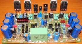
Made in Brazil!It seams they are familiar to me .....
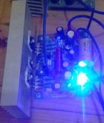
Emprit Amplifier
Simple amplifier design by me It called Emprit Amplifier.
Heatsink is undersize but only for testing.
Some of my friends built it and they like it verry much.
Simple amplifier design by me
It called Emprit Amplifier.Heatsink is undersize but only for testing.
Some of my friends built it and they like it verry much.
Attachments
.JPG)
.JPG)
.JPG)
- Home
- Amplifiers
- Solid State
- Post your Solid State pics here