apexaudio
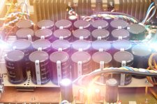
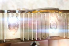
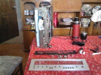
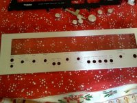
Yes it is my PSU. It is made in 70-80% from the scrap. On the board is :
-standby 15V
-temperature protection
-over load protection/ short circuit protection
-+/-15V for preamp
-another 15V AUX supply
-speakers delayed ON
-speakers fast switch OFF
-DC protection
-temperature protection for amplifier
-auxilary SMPS switch OFF trigger can be added
There is smaller version too with LLC capability.
The main board is universal, any smps driver can be adopted to run it - like in slewmaster
slewSMPS
Regards
Very nice, is there threads on forum about this SMPS ?
Regards
LM3886 XY amplifier
Hi Friends,
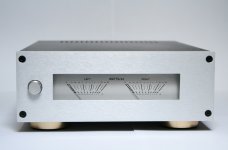
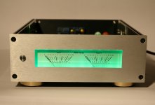
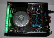
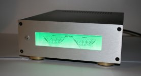
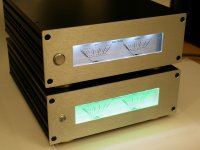
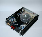
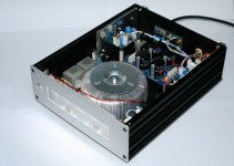
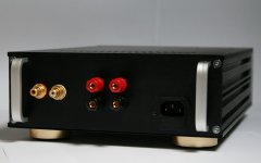
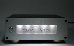
At first I want to wish you all all the best for 2016 . Thank you all for the kind words about the LM1875 amplifier. Maybe it is nice to post some pictures of another project as well. I have just completed the last one of two LM3886 based stereo amplifiers... Well finished almost, the 'green' one is still missing one of the rack handles . I expect to receive it soon. Both amplifiers perform sonically alike and look very similar, except from a few minor details. I have attached some pictures .
Regards,
Michael van den Born (PA4MW)
Hi Friends,
At first I want to wish you all all the best for 2016
. Thank you all for the kind words about the LM1875 amplifier. Maybe it is nice to post some pictures of another project as well. I have just completed the last one of two LM3886 based stereo amplifiers... Well finished almost, the 'green' one is still missing one of the rack handles . I expect to receive it soon. Both amplifiers perform sonically alike and look very similar, except from a few minor details. I have attached some pictures . Regards,
Michael van den Born (PA4MW)
Attachments
Wow - fabulous build Michael!
BTWcwhere did you get your meters?
Best wishes for 2016!
Thank you
! Both meters are salvaged from two Sony TA-212 amplifiers. The VU driver circuit is made by myself on some vero board:An externally hosted image should be here but it was not working when we last tested it.
This board also contains a latching circuit. Via this circuit the LEDs slowly fade in (about 1.5 sec) when the amplifier is turned on.
Off topic:
I just recognised that you have designed the Ovation boards Andrew! What a coincidence: I have bought the 100Wx2 Ovation nx PCB's from Jims Audio a few days ago
! It is a project for the long term, but at time I will post some updates in the Ovation thread / Off topic
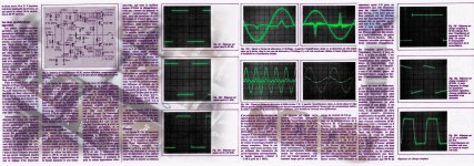
Jean Hiraga's Class A 20W Amplifier (L'Audiophile. April, 1980).
Attachments
-
 Hiraga 20W 1980_10a.jpg346.2 KB · Views: 402
 -
 Hiraga 20W 1980_05a.jpg761.8 KB · Views: 395
 -
 Hiraga 20W 1980_04a.jpg564.6 KB · Views: 411
 -
 Hiraga 20W 1980_02a.jpg568.1 KB · Views: 434
 -
 Hiraga 20W 1980_01a.jpg493 KB · Views: 442
 -
 Hir20W_a01.jpg818.4 KB · Views: 431
 -
 Hir20W ART 001.jpg483.8 KB · Views: 387
Hi. I recently saw this thread.
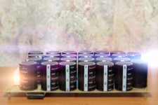
I have made many DIY but I'd like to show it where I used a Technics SA 5551 chassis 1976 vintage which was in the electronics in very poor condition and have replaced LM3886 amplifier; copy line Rod Elliot preamp; phono preamp copy of Rod elliot; Phillips tuner tuner board; all controlled by relay inputs; controlled relay loudness; Speaker protective and delay; LED lighting; AIWA toriodal transformer 280 watts. Regards.
I have made many DIY but I'd like to show it where I used a Technics SA 5551 chassis 1976 vintage which was in the electronics in very poor condition and have replaced LM3886 amplifier; copy line Rod Elliot preamp; phono preamp copy of Rod elliot; Phillips tuner tuner board; all controlled by relay inputs; controlled relay loudness; Speaker protective and delay; LED lighting; AIWA toriodal transformer 280 watts. Regards.
Attachments
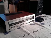
Missed photo inside
An externally hosted image should be here but it was not working when we last tested it.
Wow, such a variety of nice project over here! Hereby some pictures of my humble and recently completed LM1875 gainclone
Stunning work! Another fan of the little LM1875 here, lovely to work with and its small size allows creative compact designs such as yours. The sound is really high end and surprisingly energetic.
My little desktop build has an external power supply (+/-17V DC, XLR umbilical, 1000uF per rail inside amp) but I think yours is built in? Any issues with PSU noise getting onto the outputs with everything being so intimate in there?
Thank you
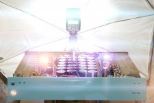
! As PSU I use a toroidal 2x 18 VAC transformer together with 2x2200uF filter caps (with 100nF in parallel for decoupling). I was expecting at least a little bit of hum because the amplifier is indeed very compact, having a gap between the transformer and PCB (the transformer is located just below the pcb) of about 1.5 cm. However, it actually does not conduct any audible hum . I have salvaged the transformer from a piece of old lab equipment (applied laser tech) that was about to be thrown away. The transformer is internally shielded quite alright, so I think that already removes a lot of noise. And of course twisting all the AC wires contributed as well Thanks Shaan! I have made a video of the LM3886 'in action' over here: LM3886 YouTube
Last edited:
The VU driver circuit is made by myself on some vero board:
Schematic please

Schematic please
For the VU-meter driver circuit I have made use of a schematic that was posted already quite a while ago on Circuits Online: VU meter circuit
However, I have changed the 22uF capacitor to 2.2uF (I think 22uF is a typo). Therewith low frequencies conducted less easily, and since power on could also be considered as a low frequency, chances emerge that your meters will fully deflect for a brief period, just after the circuit is energized. It should not really harm the meters, but ever still, better safe than sorried ;-). With 2.2uF this phenomenon dissapeared and the meters are still responding quite accurate. In addition I have also changed the 470 uF capacitor to 10 uF. At 470uF the meters respond really lazy, while they should respond quite rapid. You can fiddle a bit with this value to get the optimum result for your VU's.
Next to the VU meter circuit you can see a soft start circuit for the LEDs. This gives a nice fade in effect: Video fade in.
The fade in circuit is basically similar to this scheme:
An externally hosted image should be here but it was not working when we last tested it.
However, it could be that you have to fiddle a bit with the resistor values. For example I changed R1 to 15k and R3 to 680 ohms. The first to increase the fade in delay time (that could also be achieved by increasing the capacitor), the second because I had no 750 ohms resistor in stock
. In addition I added a little indication LED on the PCB, which is nothing more than a regular LED and a series resistor of 4.7K.Even though you made a pretty neat job to make it even more good looking you should consider logarithmic VU meter drive
That actually makes the VU meter playable almost at any level ...
I agree
For now I wanted to keep the circuit simple and compact, but for my next project I want to build something more advanced. Ultimately adding 'clip' / peak LEDs as well. Here is a nice paper with schematics: http://www.wseas.us/e-library/conferences/2011/Lanzarote/ACMOS/ACMOS-65.pdfIT can be done with far more simple ways ( obviously the target is to look nice not present the output accurately )
Probably, but how accurate are those? The one in the paper seems to have an impressive degree of accuracy. Do you have suggestions for one or more suitable circuits?
- Home
- Amplifiers
- Solid State
- Post your Solid State pics here