if anybody could EXACTLY tell me step-by-step HOW to post pictures I have on my PC, I could show you my quadruple power amp on a single 15" tall heat sink, with a beefy power supply also mounted on the heat sink (with the 35 Amps bridge rectifier UNDER the PCB - in order to screw it on the heat sink).
First goal: find out what brand & type resistors are best sounding, after that's done, the same test will be done for the electrolytics in the feedback loop (Panasonic ECA audio caps, Silmic II, Cerafine and MUSE will be put in each amp per side).
After that's done, it will serve as the low/mid, mid, mid/high and high amps in my next project: a FIVE way active system with bass extention, active subtractive filter, allpass filters, these four amps and a monster-amp for the LF section (35Hz -3dB as a standard in a closed cabinet, with 6 or 7 dB of correction this will be extended to around 24Hz -3dB).
I will use the 12" Ultimate Woofer from Morel (two per channel) because this one is thermally virtually indestructible with its 130mm(!) voice coil AND has the right parameters.
The total loudspeaker will have 9 drivers incorporated, the monster amp requires 20(!) output devices and more than 1000 Watts of transformer power. It will have rail voltages of a bit less than 100 Volts... should be able to deliver 800 Watts in 4 Ohms effortlessly")
With an active correction, you just cannot have too much power...
First goal: find out what brand & type resistors are best sounding, after that's done, the same test will be done for the electrolytics in the feedback loop (Panasonic ECA audio caps, Silmic II, Cerafine and MUSE will be put in each amp per side).
After that's done, it will serve as the low/mid, mid, mid/high and high amps in my next project: a FIVE way active system with bass extention, active subtractive filter, allpass filters, these four amps and a monster-amp for the LF section (35Hz -3dB as a standard in a closed cabinet, with 6 or 7 dB of correction this will be extended to around 24Hz -3dB).
I will use the 12" Ultimate Woofer from Morel (two per channel) because this one is thermally virtually indestructible with its 130mm(!) voice coil AND has the right parameters.
The total loudspeaker will have 9 drivers incorporated, the monster amp requires 20(!) output devices and more than 1000 Watts of transformer power. It will have rail voltages of a bit less than 100 Volts... should be able to deliver 800 Watts in 4 Ohms effortlessly
With an active correction, you just cannot have too much power...
I hear you, and Harrison.
The heat sink is on the small site. It has been playing on my mind as well.
Bear in mind that the bottom cover is cut out around the heat sink and that there is a corresponding air vent on top of the amp. So air can circulate.
But yes, when I made the enclosure I did not think ahead far enough. I did run the amp for a few hours keeping an eye on the temperature and at the listening levels I run it, there has been no issue.
I certainly take some learning from this amp build and I look forward to the next project when inspiration hits me.
Stephan

The NO1 failure in DIY projects is like that we rush to produce and test pcb and then find an enclosure to put everything inside ...In reality its the other way around First you make a proper enclosure and then produce the pcb to meet the enclosure arrangement ..
Truth is that pcb is much easier and cheaper to produce and that is driving most people to the above error
When making a post, scroll down on the screen until you can click on the "Manage Attachments" button.if anybody could EXACTLY tell me step-by-step HOW to post pictures...
After the popup screen appears, use it to upload pics in JPG format from your PC.
Preview your post with the attached pics to make sure you uploaded what you want to see in the post.
Since 1985Mister Apex with all my respect, for how long you have been designing audio amplifier and other circuits? this is a lot of motivation for me and other guys here in this forum
Regards
Juan

Since 1985
I'm glad you are sharing your ideas, thank you for doing this, is just awesome.
Regards
Vargas
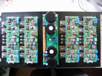
And thanks to a member here, I now know how to attach a picture of my quadruple amplifier: each amp uses Japanese, fast transistors and at the moment, four different makes resistors (one being metal film, three different carbon film resistors because suspicion has arisen these will sound better...)
To see things better, I chose a picture from before all the wiring was in place. Now I know for sure: they all work!
To see things better, I chose a picture from before all the wiring was in place. Now I know for sure: they all work!
Attachments
I have more interesting amplifiers
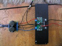
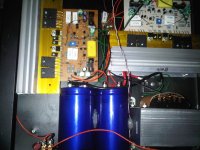
What about a simple class AB amp, mainly built with SMT parts, size of the PCB is a mere 1 1/4" X 3".
But don't be fooled: this one is capable of pushing out in excess of 250 Watts RMS(!) @ 4 Ohms. It takes a 500VA 2X 40V transformer and 2X 24000µF/63V to achieve this, however.
Those powerful Toshiba power trannies (2SA2121 / 2SC5949, 220 Watts!) make things like this possible. Emitter resistors of just 0.1 Ohms help in getting more efficiency, and generate less heat in these resistors, meaning 4 Watts will do. Thanks to the low thermal resistance in these 220 Watts transistors, there is no thermal runaway. Note: the small TO-126 transistor in the middle is the idle current regulator transistor, also keeping the whole thing from thermal runaway, the other two TO-126s are the drivers for the final stages 2SA2121 and 2SC5949. I used 2SA1358 and 2SC3421 for this purpose. Idle transistor is a 2SC3420. Input trannies are 2SA1312s and current source is built around BF620 or BF621, voltage gain stage around BF720 and BF721. Most resistors and capacitors are 0805 SMTs. On the bottom of the PCB some larger 1W SMT resistors found their home, and some film capacitors in size 2824 are also present there.
Attachments
You made me think when I got into electronics (the days of tubes only). 1967.I'm glad you are sharing your ideas, thank you for doing this, is just awesome.
Regards
Vargas
You made me think when I got into electronics (the days of tubes only). 1967.
Now that you mention that, I star it to like audio amplification when I saw a tube audio amplifier that my father made in 1956 that is way I like all about audio amplification.
Regards
Vargas
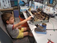
where the young meet the vintage ...
That is a precious picture - thanks for sharing!
- Home
- Amplifiers
- Solid State
- Post your Solid State pics here