This one works a bit better. And again, completely capless.
Though I would probably still opt to burn one cap upon the
altar of the bootstrap gods. Just to abuse identical mosfets.
I don't seem to need Zen upon either base follower to get
smooth results in AB. I think saturation voltage of bipolars
here might be preventing overdepletion of the gates...
If it works, I'm not complaining!
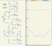
Try with .33 quiescent set resistors if you want to see AB.
I've set my sim to run in Class A. The 96KHz dummy signal
tricks LTSpice to avoid calculation shortcuts that otherwise
give spurious results. Very calming upon higher harmonics.
Though I would probably still opt to burn one cap upon the
altar of the bootstrap gods. Just to abuse identical mosfets.
I don't seem to need Zen upon either base follower to get
smooth results in AB. I think saturation voltage of bipolars
here might be preventing overdepletion of the gates...
If it works, I'm not complaining!
Try with .33 quiescent set resistors if you want to see AB.
I've set my sim to run in Class A. The 96KHz dummy signal
tricks LTSpice to avoid calculation shortcuts that otherwise
give spurious results. Very calming upon higher harmonics.
Attachments
Yeah an interstage.... 600+600+600
But I'd probably just cap couple (parafeed?) , and dumb it
down to a simple choke.
If both emitter current can be made equal enough, the 600
ohm resistor alone might be sufficient for ground reference.
Or you can abuse a normal op-amp for servo if you prefer.
But I'd probably just cap couple (parafeed?) , and dumb it
down to a simple choke.
If both emitter current can be made equal enough, the 600
ohm resistor alone might be sufficient for ground reference.
Or you can abuse a normal op-amp for servo if you prefer.
Each Aleph emitter loads the input 22K-150K depending on Freq...
If you want to knock it flat the simplest way (by resistor to GND),
means you are gonna be somewhere below 10K for Push Pull.
Probably a lot less if you care at all for strong ground reference.
You can buffer before or after the emitter junction, either way
gets input impedance up... Getting rid of bootstrap helps too.
But driving rail to rail without bootstrap is not as easy as I
had first imagined.
But the original advantage of feeding the emitter was simplicity.
I can buffer 10 different ways from Sunday, it soon becomes a
much more complicated thing. Looking less and less like Aleph.
This gets around a lot of probs, but you can see it has completely
abandoned the Aleph topology. Looking more like a pair of Nels'
later Zens....
Q3 and Q4 conduct harder than Q1 Q2 and have extra emitter
resistor to insure there is sufficient voltage offset for setting Iq
between the outputs...
Voltage gain of 2 insures the input need not equal or exceed
the output, simplifying a rail to rail drive without a bootstrap.
Schottkys are black magic for AB, maybe not a necessity for A.
I'm still not entirely sure why they have such a strong effect
upon crossover distortion? Simply narrowing the voltage gap
reference by the same amount does not have the same effect.
Otherwise, the same thing only completely different...
Attachments
I'm not sure... Neither looks enough like my own circuits
to make comparisons yet. Maybe after I've study'd them
a bit longer. Can only give my snap impression, which is
likely based on complete misinterpretation, and entirely
out of touch with your actual theory of operation.
Top schematic's VGS offset from input is an unknown
till you build it and measure... I kinda prefer bipolar
VBE (Aleph style) for standard and predictable offset.
Otherwise, I think I do get what is happening here.
Lower schematic: I might understand your bottom half
as an offset voltage follower, but the top end doesn't
quite make sense to me yet. Is it an offset follower of
voltage too? Or just a modulated current source that
lets the lower half decide the voltage?
Think I'd still use bootstraps for full swing rather than
limit pull-up with I1 and I2 CCS..
I'd need your .inc's to learn anything by simulating it.
What purpose has R6, influence lost in the much higher
collector impedance of Q3? Is it just a power dissipator?
Hi Ken,
The design thread:
http://www.diyaudio.com/forums/showthread.php?s=&threadid=99313
Simulation files and design evolution:
http://gaydenko.com/audio/ab-dynamic/
Cheers
Atiq
The design thread:
http://www.diyaudio.com/forums/showthread.php?s=&threadid=99313
Simulation files and design evolution:
http://gaydenko.com/audio/ab-dynamic/
Cheers
Atiq
Re: topology
")
The top output stage is designed by Alex Nikitin (aka x-pro), and was used by Creek Audio. The bottom one - by me, and was used by me and other russian diyersOriginally posted by atiq19 How does this topology compare with your one?
Took me a while to get that one biased correctly for smooth AB
(with LTSpice default components, since I don't have your libs).
I notice probs driving toward the negative rail. You can't swing
your input past the gate drive voltage of the lower MOSFET. Its
not an issue that can be resolved by bootstraps as the upper
half's CCS's lend themselves so well.
(with LTSpice default components, since I don't have your libs).
I notice probs driving toward the negative rail. You can't swing
your input past the gate drive voltage of the lower MOSFET. Its
not an issue that can be resolved by bootstraps as the upper
half's CCS's lend themselves so well.
If the lower half of your circuit were upgraded with an Aleph,
configured as the offset voltage follower. Then you would not
only be able to swing that part of your circuit within a volt of
the negative rail, but plausibly claim the updated schematic
might then have relevance to Pass threads.
The upper half of your circuit was the unique part anyway.
Strange way to derive class AB... But no stranger than my
Schottky's. It does seem to work, and reasonable to ask
how it compares.
I don't need any Aleph-related schematics parts, ideas etc And I have own view to the amplification, "sounding", realization and so on. In particular, I like and want to listen to DC amplifier without those heap of capacitors. Please, follow the appropriate thread related to the AB-dynamic (the href was cited above).
And I have own view to the amplification, "sounding", realization and so on. In particular, I like and want to listen to DC amplifier without those heap of capacitors. Please, follow the appropriate thread related to the AB-dynamic (the href was cited above).OK, you don't care for Aleph's bootstrap caps, I can dig that...
I think I've already shown more than one way how to get rid
of Aleph's caps (if its still an Aleph afterward?). Would get you
3V closer to your neg rail without upsetting how your upper
circuit derives class AB.
I think I've already shown more than one way how to get rid
of Aleph's caps (if its still an Aleph afterward?). Would get you
3V closer to your neg rail without upsetting how your upper
circuit derives class AB.
- Status
- This old topic is closed. If you want to reopen this topic, contact a moderator using the "Report Post" button.
- Home
- Amplifiers
- Pass Labs
- Possible improvements for Aleph?