Johannes, is there a specific reason why the IRFP9240 does not perform well? I do not have much knowledge about FET's so that's why I ask....I would not use IRFP9240 as the bottom P-channel fet.
With an IRF4905, IXYS IXTP32P05T or other similar low voltage high power P channel device the distortion drops substantially compared to the IRFP9240.
I will let Nelson Pass answer that question. He does it much better then me:
http://www.firstwatt.com/pdf/art_zen_redux.pdf
Cheers,
Johannes
http://www.firstwatt.com/pdf/art_zen_redux.pdf
Cheers,
Johannes
I found a 50 VA 230 - 230 volt toroid transformer in my big box of parts, so I have been trying to come up with a simple way to implement PCF in a single stage, single active device amplifier (Zen) with a transformer based phase inverter.
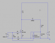
This is where I ended up. I have not yet tried this, but since all I need is a single 1.0 ohm power resistor (R-sense) and a transformer I hope I can manage to point to point solder in those two components today into my simple test-amp with the IRLB3813 I have been exploring in another thread.
The toroid mains transformer is probably not nearly as good as a nice Jensen or Edcor but it is what I have at home. It will hopefully give an indication of potential performance.
Cheers,
Johannes
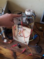
A nice spectacular fail...
I have no idea if it is my beautiful perfect layout, the short leads, the extreme high quality transformer or just having two large coils near each others without any magnetic shielding at all, but all I got was a not so nice oscillator.
I tried to reverse phase several times back and forth and I tried with 1.0 ohm R-sense and 0.5 ohm R-sense. With 1.0 ohm it oscillated violently regardless of phase and with and without signal. It was a very high pitch very powerful shriek. Totally unbearable.
With 0.5 ohm R-sense I could get it to play music. I guess it was oscillating at very high (RF) frequencies since it sounded very strange, very hollow, shrill and jarring.
If I reversed phase it started to oscillate at a very high frequency within the audio-band and the oscillation was nicely modulated by the music. With a mile long antenna I could have broadcast VLF amateur AM transmissions. I wonder what the Swedish "Post och telestyrelsen" would have though about some sudden 3 watt VLF transmissions playing Skinny Puppy with very bad bandwidth and lots of distortion?!?
https://en.wikipedia.org/wiki/Very_low_frequency
It was a fun experiment. Well worth the time and the 3 cm of solder tin.
Johannes,
Sorry to trouble you again.
I refer to your schematic in post 119.
My power supply is 24 V dc.
For M1 , I use IRF 4905
For M2 and M3, I use IRFP9240.
Is this Ok?
Any other value to change?
Is it realistic to expect 10 W out put for my 92db Markaudio 12P?
thanks
kp93300
Sorry to trouble you again.
I refer to your schematic in post 119.
My power supply is 24 V dc.
For M1 , I use IRF 4905
For M2 and M3, I use IRFP9240.
Is this Ok?
Any other value to change?
Is it realistic to expect 10 W out put for my 92db Markaudio 12P?
thanks
kp93300
My power supply is 24 V dc.
Is it realistic to expect 10 W out put for my 92db Markaudio 12P?
No. With only 24 volts power supply you will get 3 watts or so.
The bottom p-channel mosfet (IRF4905) steals 4 volts of power supply voltage without adding to the available output voltage swing. It is a trade-of to get an easy way of implementing positive current feedback and Schade feedback in the same simple circuit without resorting to expensive Jensen signal transformers or other more complex circuitry.
For M2 and M3, I use IRFP9240.
Is this Ok?
Any other value to change?
The IRFP9240 is a P-channel mosfet. M2 and M3 is N-channel parts (IRFP240 - 250 - 150 - 7430 - 044 - 054 etc).
If you want to use cheap standard IR parts in a TO-247 package use the IRFP054 or IRFP150 instead. You really need the high transconductance to avoid excessive amounts of distortion. Don't be afraid of the high Ciss of these parts since you drive the gate from the amp output in a very low resistance Schade feedback-loop. You can use 20 paralleled IRFP054 without any problem with excessive input capacitance (just lower the Schade feedback resistors - R9 and R10 - to 47 ohms and 4,7 ohms).
You are of course free to test the amp with the IRFP240 devises, but I know you will be disappointed, and I am afraid you will blame my "strange" circuit for the lacklustre results.
Cheers,
Johannes
R2 and R3 sets the amount of current. You can adjust this for more or less current, based on you needs (heatsink, impedance of your loudspeakers etc).
With R2 = 0.5 and R3 = 0.33 i get 1,6 amps of quiescent current.
With R2 and R3 = 0.5 ohm you get about 1.2 ampere of quiescent current (with IXTK100N25P M3). This will change a little based on the Vgs of the device you use for M3.
If you use 3 watt metal-film power resistors then it is quite easy to adjust this. 2 paralleled will result in 0.5 ohm. 3 paralleled results in 0.333 ohms and so on.
R2, R3 and R4 all need to be at least 3 watt power resistors. I use multiple paralleled 3 watt types to keep them reasonably cool.
R12 is the loudspeaker.
I recommend using a 300 ohm resistor to ground from the output node of the C2 to bleed of any voltage there if there is no loudspeaker attached.
In short I recommend following all the advice from Nelson Pass excellent Zen amplifier article series. It is a simple Zen amplifier with a bottom P-channel mosfet, PCF and low resistance Schade feedback loop added.
Please pay attention to the way the bottom P-channel fet (M1) has its source coupled to the source of M2. It is source to source. Not drain to source as in a normal cascode.
Cheers,
Johannes
Hello Johannes. Regarding the circuit in post 124, its amp may not oscillate if the ground/common of the transformer windings are separated. And R7 [100 Ohms] is converted to a variable resistor to fine tune the level of PCF.
I use a toroid for isolation of grounds. Other wise my amps often oscillate; maybe due to ground loops.
I use a toroid for isolation of grounds. Other wise my amps often oscillate; maybe due to ground loops.
amp may not oscillate if the ground/common of the transformer windings are separated. And R7 [100 Ohms] is converted to a variable resistor to fine tune the level of PCF
Thanks for the suggested solution. It was a just a fun and cheap 10 minute experiment. Ground loops is definitely a potential creator of oscillations. I guess I need to terminate the secondary winding of the transformer much better. I did not use 100 ohm as in the schematic. It was a 10 k resistor (when I measured it later). With a large low DCR aircored coil just 5 inch away from the transformer I am surprised I did not blow the gate of the mosfet the exact instant I applied power to the amp. With one ohm R-sense it was quite violent. It was a very powerful oscillator. It started to oscillate with a beastly furiosity, and I guess it got quite close to the max voltage Vgs of the IRLB3813.
I am still curious of the potential performance of a transfomer-coupled PCF Zen amp. With a nice large bandwidth and low distortion bifilar wound Jensen transformer I believe it can sound very nice. Transformers are fun, but the shipping cost to Sweden is too expensive for some fun and cheap experiments. The P-channel mosfet is cheap, easy and a linear device for PCF, without the inherent tendency to create AM-transmitters out of any non-linearity and stray capacitance or inductance in cables, active devices, powersupplies etc...
I learned that it is possible to use a transformer as a phase-inverter for positive current feedback. I guess it is possible to use the same Schade feedback Nelson Pass used in the BAF2015 amp, and couple some PCF into that transformer.
There is a lot of potential fun to be had with this.
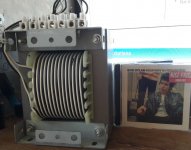
I have been trying to find a suitable simple balanced PCF SoZ circuit for my large bifilar wound transformer cored inductor.
It is a heavy 1400 VA 20 kg transformer-core. Perfect for a SoZ V-7 T with SUSY feedback and PCF.
Cheers,
Johannes
While waiting for my IRFP7430 I have been thinking about what kind of amp I want to test these new strange devices in. I am jumping back and forth between trying to keep it as simple as possible and trying out exciting things like PCF, Bastode and Cascode circuits.
In post #641 in the First Watt F7 Review thread Nelson Pass wrote this:
I prefer the very open and alive, effortless character of a good triode (or SIT) amplifier without negative feedback, and I hope I can use the IRFP7430 in something along those lines.
The IRFP7430 has a ridiculous amount of gate capacitance. This is easy to drive with some input buffer. An IRL510 running at 100 mA would drive this gate-capacitance with ease, but I don't like using an input buffer. I don't know why. I just have this feeling of disapproval whenever I start simulating an input buffer. It is not very scientific or even logical, but sometimes I just go with that kind of feeling and afterwards I often find out that it was the right call.
The Bastode circuit I have used in my amps I have built and written about in this thread, solves a lot of the potential problems with these new devices. It has a DC coupled input. It is easy to drive the gate of the IRFP7430 from the output of the amplifier with very low resistance feedback loop or just a resistive voltage divider if I don't want any global negative feedback. It is easy to tune the amp with PCF and/or filters in the positive feedback loop. It has lot of potential for fun experiments.
This is where I ended up in LTSpice:
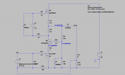
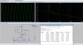
At least it looks real good in simulation. I did not use the IRFP7430 in my simulation since it is not in the LTPice standard library. I guess the IRFP7430 will have more distortion then this. I will have to play around with the device some before I settle on the exact design.
Cheers,
Johannes
In post #641 in the First Watt F7 Review thread Nelson Pass wrote this:
There is no requirement that the amplifier has to have a negative feedback
loop. If you can make a decent amplifier without it, then you can apply
positive current feedback.
I prefer the very open and alive, effortless character of a good triode (or SIT) amplifier without negative feedback, and I hope I can use the IRFP7430 in something along those lines.
The IRFP7430 has a ridiculous amount of gate capacitance. This is easy to drive with some input buffer. An IRL510 running at 100 mA would drive this gate-capacitance with ease, but I don't like using an input buffer. I don't know why. I just have this feeling of disapproval whenever I start simulating an input buffer. It is not very scientific or even logical, but sometimes I just go with that kind of feeling and afterwards I often find out that it was the right call.
The Bastode circuit I have used in my amps I have built and written about in this thread, solves a lot of the potential problems with these new devices. It has a DC coupled input. It is easy to drive the gate of the IRFP7430 from the output of the amplifier with very low resistance feedback loop or just a resistive voltage divider if I don't want any global negative feedback. It is easy to tune the amp with PCF and/or filters in the positive feedback loop. It has lot of potential for fun experiments.
This is where I ended up in LTSpice:


At least it looks real good in simulation. I did not use the IRFP7430 in my simulation since it is not in the LTPice standard library. I guess the IRFP7430 will have more distortion then this. I will have to play around with the device some before I settle on the exact design.
Cheers,
Johannes
I have a couple of questions regarding your circuit in post 119. Your bottom fet has both the input from the source device as well as the PCF from Rsen. You show the negative of the input ac source as referenced to the top of Rsen rather than ground. Does the 22k R13 act as both a feedback R as well as a Load resistor for your source and what is the input impedance. Is the 220 gate resistor large enough to avoid cable issues, etc. And does increasing it cause any issues. NP often uses 1k on the smaller input fet' he uses as buffers. Finally do you have any formulae for determining Rsen for various types of speaker loads or can we use some form of variable resister to fine tune the amp as others have done in the F6 with PCF. Sorry for what may seem like stupid questions but I am having a bit of trouble understanding the circuit which to me looks very interesting. I have a Zen 9 very much in need of some upgrading.
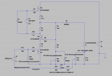
I re-drew this schematic with some small changes.
R16 is connected to true ground. It is probably more secure and more stable then routing it all the way to the output R-sense. It is only there to secure a good connection and 0 volt connection for the P-channel fet gate. The value 22 kohm is not that important. You can use anything between 1 kohm to 100 kohm. It kind of sets the input resistance before the the PCF. PCF will increase the input resistance substantially.
R12 is a 100 ohm 2 watt linear potentiometer. It is an easy way to adjust the amount of PCF. I added some RCR filtering (R13 R14 and C3) to tame the top end. It seems to be needed for the F6 so it is probably needed for this amp to.
M1 is a P channel device. I would use a low voltage high current type like the IXYS IXTH140P05T or the IRF4905. Look for -4 volt Vgs (or more) and lots of transconductance.
M2 and M3 are N-channel devices. IRFP150, IRFP054, IXTK170N10P, IXTH340N04T4 and many more similar devices would probably work fine. I prefer low voltage, high current, high transconductance parts like the IXTH340N04T4, since you need some real muscle if you want to keep the distortion down while using PCF to increase the damping factor.
Sorry for what may seem like stupid questions but I am having a bit of trouble understanding the circuit
There is no stupid questions. We are all here to learn. I know I am not very good at explaining my ideas in English. It is not my native language.
I am just happy someone is showing interest in my circuits.
Please ask any and as many questions you need to. I will try to answer them.
Cheers,
Johannes
R17 (input resistor) is the corresponding "1 kohm resistor" Nelson Pass often uses on the input. I have heard my amp oscillate wildly without it once or twice, but since I never use my amp more then a few days (I am always testing new ideas) I seldom care to use this resistor. Use whatever value you feel comfortable with. A high resistor value will dampen the high frequency response. A low value might not prevent oscillations with certain cables or preamps.
I would probably use something between 100 ohm and 470 ohm, depending on the length and type of cables I will connect to the amp.
Cheers,
Johannes
I would probably use something between 100 ohm and 470 ohm, depending on the length and type of cables I will connect to the amp.
Cheers,
Johannes
Thanks, but after some more thought it appears the 13.5 nF capacitance of the 140P will require some sort of driver to avoid the high frequency roll-off. Probably back to the n and p jets or the transformer. I still like the idea of injecting both the input signal and the PCF into a common drain device and using Shade feedback to make the common gate driving device act like a triode. I also think the input ground for your source component ( pre-amp, dac, etc ) needs to connect to the ground of your amp or ground loops and other problems will occur. Your way keeps the amp non-inverting.
the 13.5 nF capacitance of the 140P will require some sort of driver to avoid the high frequency roll-off.
When running my amp directly from the soundcard in my computer I have a simulated -3dB point of 130 Khz. I use a 220 ohm gate resistor.
I don't consider this a problem. I would not use a passive preamp (10 kohm potentiometer) though.
I choose the IXTH140P05T because I want lots of transconductance. I guess you could use an IRF9540 if you wanted. I have tried an IRF9530 and it worked as it should. With lots of PCF for a slightly negative output impedance there was a little more distortion then I liked.
Cheers,
Johannes
What is the operating temperature of the various transistors?
I don't have any measurements of the exact temperature.
I try to run them cool enough that I can hold my finger on them for 5 seconds. I guess this is somewhere around 50 - 55 degrees Celsius.
The IXTK100N25P seems to be able to take a lot of both heat and power. Quite tough devices. The TO-264 is easy to mount and cool.
I have enlarged the holes to 4.1 mm so I can use M4 bolts and large washers, for some real mounting pressure.
Cheers,
Johannes
I read up on the Bastode circuit which was unknown to me and I think I see the logic. Basically acts in your case as a source follower driving the signal into the source of the amplifying device and shielding it from its gate capacitance. I presume the gate capacitance of the p-Fet is not a problem as the signal is not being amplified there. I like your variable idea and would use it and would increase R17, R13 and R14 to 470 ohms. I have had cable problems with less than 250 but not with 470 or higher. I would put the feedback directly to the junction of R17 and R5 and leave my load R16 at around 25k as you suggest. This seems quite elegant as we avoid buffers and transformers and can use Shade feedback. Better get to work. Thanks for your suggestions.
I wish Nelson Pass would present this idea as an article in his Zen series of single stage class A amps, since I know it would get the attention it really deserves by coming from someone known and respected and not only from some eccentric unknown Swedish guy.
It seems to me that you are doing a perfectly fine job with this.
I wish Nelson Pass would present this idea as an article in his Zen series of single stage class A amps, since I know it would get the attention it really deserves by coming from someone known and respected and not only from some eccentric unknown Swedish guy.
I feel your pain. Hahahaha
I haven't been following your thread, but only cause I'm too busy with my own ideas.
It's probably the most logical/applicable use of pcf I can think of.
The real reward is building it for your own enjoyment.
- Status
- This old topic is closed. If you want to reopen this topic, contact a moderator using the "Report Post" button.
- Home
- Amplifiers
- Pass Labs
- Positive Current Feedback simple Zen amp