
following with Interest!!
very interesting stuff...this could be the amp that I have been longing for ...I need at least 25watts for my stuff
maybe you could model something along these lines...I am a beginner to amplifier design/understanding.... so a very steep learning curve ..I love to learn
I really like the idea of being able to control the amp in many different possibilities neg feedback is a 2 dimensional tool....pcf is looking like the 3rd dimension!!
Lawrence
A few of these: http://ixapps.ixys.com/DataSheet/DS1...10N20L2).pdf
could be nice. I recommend watercooling.
Nice ! This one reminds of the part that mr Pass uses in "BAF 2015 singel end amp"
Hmmm... maybe a new project..
/ tord
could be nice. I recommend watercooling.
Nice ! This one reminds of the part that mr Pass uses in "BAF 2015 singel end amp"
Hmmm... maybe a new project..
/ tord
maybe you could model something along these lines...
You are free to use any of my designs I post in this thread. I am not a designer or any kind of engineer. I can't recommend anyone else to build my designs, and I can not design amps for other people. I can not take any kind of responsibility or guarantee any kind of results. I only want to encourage people to play with this PCF thing. I have found what I consider a smart and very useful way of implementing PCF. If you can build a normal Zen amp, then it is quite easy to add a p-channel fet between the source of the gain device and ground, and attach the gate via a 300 ohm resistor to a sensing resistor between the speaker and ground.
These amps a quite stable and fault tolerant, so they make a great platform for experimentation.
pcf is looking like the 3rd dimension
I good analogy. I agree. It is whole new axis of possibilities.
Nice ! This one reminds of the part that mr Pass uses in "BAF 2015 singel end amp"
I saw the youtube video yesterday. It seems like a great amp. I would love to have some of those new SITs...
Cheers,
Johannes
Last edited:

I built this very simple no negative feedback Zen amp yesterday.
I want to test the Cree SiC device to get a feeling for the sonic character of it.
I am very impressed. It is very smooth, low distortion and nice sounding device.
I run 620 mA of current through it. I would call this too a torture test. I want to squeeze it a bit to see how it reacts. Even an IRFP240 can sound marvelous with enough current and voltage in comparison to the load it is supposed to drive.
IR parts sound very harsh with a lot of high ordr harmonics when starved of current.
This SiC part does distort (as expected), and especially when playing loud and with some heavy bass.
When playing voices, saxophone or grand piano at moderate listening levels it shines.
The distortion is very simple second harmonic. With complex music it sounds a little blurred and muddy. But unlike an IRFP150 in the same circuit there is virtually no higher order harmonics. It is very easy to listen to for prolonged periods of time. The IRFP150 sounds harsh and intrusive. Everything gets a abrasive edge with the IR part with this little current.
My initial opinion about this SiC device is that it is a very affordable and good sounding device. Nice highs. A very smooth and fluid character. Easy to listen to for prolonged periods of time. With some real current and a more proper design I am sure it can be the foundation for a great sounding amp.
I am even tempted to build a simple class A/B push pull amp with two of these.
Cheers,
Johannes

NB that PF isn't so novel thing in Papa's Realm ;
Aleph CCS active operation is based on load dependable PF
J2 is also using load dependable PF for it's upper half active operation
not exactly as last emergency box containing magical resistor opening , but certainly trick already used by Mithrandir
(didn't check what polarity of cascode modulation is in F3 and latest XS happenings , but ..... )
Today I watched the youtube video from BAF 2015.
https://www.youtube.com/watch?v=wa_k0abLpAU
Nelson Pass talks about how some simple Schade-feedback turns a simple penthode curved device (most mosfets) to something very closely resembling a SIT (triod-curves).
He says he could not see any difference between a real SIT and a Schaded IXYS device in distortion character, transfer curves etc, but he got a better damping factor from the Schaded IXYS device.
If some Schade feedback can do that, I want to Schade my Cree SiC fets.

The N-channel device would be the Cree in my amp. I used the standard library in LT-Spice for the simulation.
This could be interesting. I know what I am going to do tomorrow.
Cheers,
Johannes
https://www.youtube.com/watch?v=wa_k0abLpAU
Nelson Pass talks about how some simple Schade-feedback turns a simple penthode curved device (most mosfets) to something very closely resembling a SIT (triod-curves).
He says he could not see any difference between a real SIT and a Schaded IXYS device in distortion character, transfer curves etc, but he got a better damping factor from the Schaded IXYS device.
If some Schade feedback can do that, I want to Schade my Cree SiC fets.
The N-channel device would be the Cree in my amp. I used the standard library in LT-Spice for the simulation.
This could be interesting. I know what I am going to do tomorrow.
Cheers,
Johannes

View attachment 538715
With the right devices.
This is not a final design in any way.
I just wanted to update the amp to what I will use in real life.
Cheers,
Johannes
When you´ve optimized the construction I think I am going to order some parts..
When you´ve optimized the construction I think I am going to order some parts..
+1
If some Schade feedback can do that, I want to Schade my Cree SiC fets.
I was going to suggest that...
A stock Zen amp is of course a Schade feedback circuit, but as every distortion vs frequency measurement clearly shows is that the usual 10 kohm + 1kohm resistor voltage divider network is reasonable compromise between input resistance and top end performance. This is also why a IRFP044 is a superior device to the IRFP240 (the IRFP240 has less transconductance compared to Ciss, Coss and Crss) for low distortion in the measured top end performance.
What might not be as obvious from the measurements is the subjective impression of a graininess or coarseness that follows with a high resistance Schade feedback loop. This does not only effect the treble but can be heard in the midrange too. It makes a grand piano or saxophone sound a little bit “edgy” and intrusive, and with a lot of positive feedback this is effect is amplified and much more pronounced.
If the resistor feedback network is lowered by an order of magnitude to 100 ohm + 1 kohm then a lot of that subjective coarseness vanishes.
This is more pronounced with IR parts (IRFP150/140/250/250/044) then IXYS devices or SiC mosfets or jfets, which is the non-linearity of the capacitance of the device messing with the transfer curve and transconductance.
I guess this is a large part as to why we prefer the much more linear SiC fets.
They have less capacitance and the capacitance that is there is more linear.
Even if the SiC has less need of a low resistance Schade feedback network, I guess it will not hurt performance at all to drive them with 100 ohm + 1 kohm (or less) feedback-resistors.
As the positive current feedback has a tendency to intensify and exaggerate the character of the device, I want to work hard to linearize the amp as much as possible before the introduction of positive current feedback.
This will enable a larger range of possible combinations of positive and negative feedback without stressing the amp into excessive distortion and a too pronounced character. It is actually quite stressful to demand both low distortion and a low output impedance from a single mosfet. In my experience it is important to use a powerful low voltage and high transconductance device. I am actually worried that the Cree SiC fet is not powerful enough. I can always parallel several of them for a large increase in transconductance and gain.
I wish they would make 100 volt SiC parts with a transconductance of around 50 S or so.
Just explaining my reasoning behind this buffered Schade feedback.
Cheers,
Johannes

Today I tested a simple MU-follower based on some stuff I had lying around.
The IRF3706 is a interesting little device. With only 1,62 volts Vgs and Vds it will sink 1,3 ampere with ease. It is very powerful at low voltages.
I bought 10 of these when they where available, because I wanted to use them in cascode with other devices.
Since my little test platform only runs at 15,5 volts, I thought it to be a suitable device.
The Mu follower made my amp much more powerful and aggressive, but the distortion increased quite a bit. I prefer the amp with a simple power resistor, despite the radically increased power available with a Mu follower.
I guess I need to test this with some feedback and with some more current and voltage.
Cheers,
Johannes
Increased distortion? That`s odd. Any measurements?View attachment 538873
Today I tested a simple MU-follower based on some stuff I had lying around.
The IRF3706 is a interesting little device. With only 1,62 volts Vgs and Vds it will sink 1,3 ampere with ease. It is very powerful at low voltages.
I bought 10 of these when they where available, because I wanted to use them in cascode with other devices.
Since my little test platform only runs at 15,5 volts, I thought it to be a suitable device.
The Mu follower made my amp much more powerful and aggressive, but the distortion increased quite a bit. I prefer the amp with a simple power resistor, despite the radically increased power available with a Mu follower.
I guess I need to test this with some feedback and with some more current and voltage.
Cheers,
Johannes
Increased distortion? That`s odd.
Not really.
The Mu-follower senses whatever happens at the output node between the two resistors.
If the amp lacks any feedback mechanism there is no way for it to control whatever mischief the Mu-follower and the reactive load (loudspeaker) creates.
The Mu-follower is not inherently linear in the same way as a constant current source or a simple power resistor. It will amplify whatever signal it receives, and if that signal is distorted, then so is the total output.
I don't mean to denounce the Mu-follower. It did not work the way I hoped in my little test setup, under some rather extreme circumstances.
Cheers,
Johannes
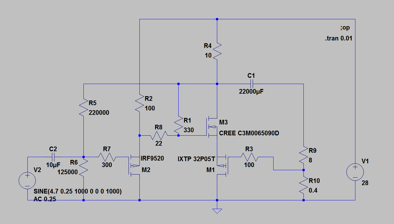
I would use 10 parallel 100 ohm wirewound 11 watt ceramic for R4 and three parallel 330 ohm wirewound 11 watt resistors for R2.
This is not an optimized design. I would recomend a constant current source instead of R4. The basic CCS from the original Nelson Pass Zen amp should work like a charm.
This is not an optimized design. I would recomend a constant current source instead of R4. The basic CCS from the original Nelson Pass Zen amp should work like a charm.
- Status
- This old topic is closed. If you want to reopen this topic, contact a moderator using the "Report Post" button.
- Home
- Amplifiers
- Pass Labs
- Positive Current Feedback simple Zen amp