The datasheet for that transformer you are using indicates it is not very efficient, only 30%, which means that 70% of the power it uses goes to heat - 1.6W of no-load loss. So that explains why it gets so warm.
Consider running a tiny buck converter off the SMPS 48VDC output instead of a transformer from 230VAC mains. These can be found cheap on ebay and small enough to wedge into your case")
Also, if the circuit can run at lower voltage, e.g., 3.3V, that should reduce heat too.
Consider running a tiny buck converter off the SMPS 48VDC output instead of a transformer from 230VAC mains. These can be found cheap on ebay and small enough to wedge into your case
Also, if the circuit can run at lower voltage, e.g., 3.3V, that should reduce heat too.
Last edited:
yeah i noticed the efficiency just now.
i cant use the 48v psu output, as the idea is it switches off the amps instantly when the mains goes down -before- the 48v output drops out. so i need something that directly senses or reacts to the presence of mains. im also limited in space, whatever i replace that trafo with must occupy a similar volume.. a wall wart would be too big, and from my experience of 5v chargers, the output would remail high for an appreciable time after shutdown..
is the optoisolator i linked to suitable? seems to be, designed specifically for mains line sensing. and its certainly small and wont get hot (i dont think..? )
i also considered a mechanical solution, microswitch linked to power button somehow, but thats not very elegant, and would not deal with power outages.
Was just reading that fairchild MID400 datasheet and the part requires 5V for VCC, it's not AC powered. So you would still need 5V from somewhere. Since you've already built the circuit, the MID400 would only help reduce footprint in your case.
These 5V converters are tiny
These 5V converters are tiny
i worry that these tiny smps'es contain significant capacitance, and might give output for some time after ac is cut..?
having said that, the datasheet for this one:
IRM-01-MEAN WELL USA Switching Power Supply
says it has a "setup/rise time" of 600ms (means startup delay? that is fine.)
and "hold up time" is 40 ms at 240v.. (is this the shutdown time?)
the 9v one is 72% efficient, which is a bit better than the trafo and a drop-in replacement
however its a bit bigger (3cmx2cmx1.5cm) which, unbelievably, is probably too big. i was hoping to find something equal or smaller than the trafo (2cm/2cm/1.5cm)
-the one you linked is small enough, but it seems that *does* have some significant capacitance. 100uf on output side might retain power for quite a while in my low drain circuit.
thoughts?
I have used those Mean Well IRM power supplies and they work well.
Unfortunately, "hold-up time" doesn't really help to understand how long takes to drain.
Regarding output capacitance...even the IRM-01 has caps, you just can't see them. Those have to be there for any smps.
The question really is, would the tiny smps drain faster than the large smps...probably, but can't tell without trying.
If it were me, I'd use the IRM-01, no contest...less EMI and known to be reliable. Pity it's 1cm over your space budget!
Thinking more about what you are trying to do - switch RESET in/out with AC mains - another possibility could be to forego the voltage sense circuit and use a simple relay across AC mains.
You would need a relay with 230V coil, "form C" which means pins for both NC normally closed and NO normally open.
TE RT314730
You would connect the relay across AC mains and wire RESET through the NC pin. When AC is present, RESET will be ungrounded.
So this would work for shutdown pop...instantaneous RESET on loss of AC power.
You could retain your sense circuit for startup if necessary. I have never had any issues with startup noises with the evm with many different power supplies, but yours may be different.
Thinking more about what you are trying to do - switch RESET in/out with AC mains - another possibility could be to forego the voltage sense circuit and use a simple relay across AC mains.
You would need a relay with 230V coil, "form C" which means pins for both NC normally closed and NO normally open.
TE RT314730
You would connect the relay across AC mains and wire RESET through the NC pin. When AC is present, RESET will be ungrounded.
So this would work for shutdown pop...instantaneous RESET on loss of AC power.
You could retain your sense circuit for startup if necessary. I have never had any issues with startup noises with the evm with many different power supplies, but yours may be different.
i was researching relays actually, i had the same thought as you. however i didnt manage to find any "subminiature" ones with a 240v ac coil.. you seem to have
wonder if it would be available to buy in europe. next question however is wether having the relay coil active all the time will get as hot as the tiny transformer...?
You could retain your sense circuit for startup if necessary. I have never had any issues with startup noises with the evm with many different power supplies, but yours may be different.
you might well be right, but i wish to cover all possible abuse/ child button pressing /power cuts etc etc..
and its not only the amps, ive got a minidsp, a bluetooth module, and an htpc. the minidsp and bt module startup from the same psu.
idea is the amps switch on after all the other junk has had time to settle down, and off before any of them start to be power starved.
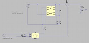
however id note that as it stands that circuit does not function in spice. im a noob and it keeps banging on about floating nodes, of which there are none that i can see. .
also, i would use an ac opto, not a dc one with an extra diode. i looked at importing an specific opto into spice, but it seemed way more trouble than its worth.. surely in 2018 it should just be a case of dropping a file in a folder..
also, i would use an ac opto, not a dc one with an extra diode. i looked at importing an specific opto into spice, but it seemed way more trouble than its worth.. surely in 2018 it should just be a case of dropping a file in a folder..
Last edited:
For my 3255 EVM board, these are the parts I used with a 1 amp 5v USB power supply hooked to mains switch:
Arduino Nano V3.0
Amazon.com: For Arduino Nano V3.0, Elegoo Nano board CH340/ATmega328P without USB cable, compatible with Arduino Nano V3.0 (Nano x 3 without cable): Computers & Accessories
1 Channel Relay Module Board
Amazon.com: DAOKI 5PCS 5V One 1 Channel Relay Module Board Shield with optocoupler Support High and Low Level Trigger: Car Electronics
On the 3255 I hooked pins 10 to NC and pin 4 to Common on the amp Audio Interface Header. Write a simple 7 second delay on the Nano and which ever pin you choose to the relay, and the relay will stay closed, and after 7 seconds, opens the relay and breaks the connection. When you turn off the mains switch, the USB power supply turns off the NANO and the relay, and the amp mutes again before the Amp power supply finally ramps down.
Works well. I can post a code if your not familiar with Arduinos.
Last edited:
thanks, it seems your system is very similar to mine, apart from i use a 555 for the delay, and a small mains transformer for the cut-out, you use and arduino for the delay and a usb supply for the cutout.
its good to hear a usb supply will ramp down faster than the main psu, but i guess that depends on the load its connected to.
in my case, since ive already got a system that works perfectly, im looking for something to replace the sense trafo on the same circuit ( 555 based) with minimal modification.
id also like something as compact as possible as that area is quite congested in my amp and not only is the trafo getting (very) hot, its also blocking most of the small amount of airflow that reaches the aux voltage regulators on the psu. those too are getting very hot, despite a tiny load. partially due to blocked airflow, and partly due to being 1cm from a 90C trafo in a confined space!
seemed to me an optoisolator and a couple of external components is a common way to sense mains, and can be absolutely tiny.. but im not getting much encouragement for this approach.. maybe there is some issue im unaware of.
Good! glad things are working well. I had no need for a sense circuit with the reset relay. Did you do your sense circuit on a PCB or Point to Point? I have had flux mess things up sometimes. Something is not quite right. Shouldn't get that hot..
The USB power supply shuts off almost instantly. You can hear that nice relay click
The USB power supply shuts off almost instantly. You can hear that nice relay click
he i went oldschool, veroboard
however the trafo is seperate, with point to point wiring for the mains side, so nothing to be "wrong" its just two wires connected to the mains ..
as poited out earlier, its only 30% efficient, and in a zone with restricted airflow and a plastic case, i think thats enough to ramp up the temperature.
Check out this CUI PBK-1-5 5v power supply.
It's a completely different form factor that you might be able to squeeze in.
It's a completely different form factor that you might be able to squeeze in.
yeah thats definitely better.. i could probably fit that in. but.. optoisolator not a better choice in my case? sorry im banging on, just seems more elegant, and tiny, and cooler running, and quicker to react, than any kind of power converter... i really dont need *any* milliwatts! if there is some reason why i should not use an opto, please educate me, as almost every suggested "ac line sensing circuit" i see online uses an opto, and it seems it would be relatively simple to integrate into my existing circuit, could probably remove half the components and make it even smaller.....?
LTV-814 Lite-On | Mouser Europe
this is an ac one, just needs a big resistor between it and the mains (apparently)
the output side can be used to switch the output of the timer to the relay.
as per this suggested circuit:
opto isolator - AC detection for microcontroller - Electrical Engineering Stack Exchange
this is an ac one, just needs a big resistor between it and the mains (apparently)
the output side can be used to switch the output of the timer to the relay.
as per this suggested circuit:
opto isolator - AC detection for microcontroller - Electrical Engineering Stack Exchange
I've been studying the schematics trying to determine why the onboard voltage supervisor doesn't engage RESET in time to eliminate shut-down pops. Here's how it works (this is all on pages 18-19 in the evm manual):
Main voltage PVDD comes into the board and there are some filter caps.
PVDD then goes to a LM5010ASD step-down converter that outputs 15V.
15V then goes into a LM2940IMP-12 voltage regulator to create the 12V rail.
15V goes into a TLV1117 LDO to create the 3.3V rail.
The voltage supervisor is a TPS3802K33DCKR which draws from both the PVDD supply and the 15V supply.
This part resets at 2.93V, and that is where the problem comes from - it takes too long to drain PVDD and LM5010ASD before dropping to 2.93V to TPS3802K33DCKR.
Perhaps it was done this way because the board supports a pretty wide voltage input of 18V to 51V.
To address the issue, 2 strategies to speed response time:
1. Move voltage detection before the 15V DC converter
2. Tune the circuit to respond to voltage drop at higher voltage
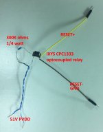
So today I proof-of-concepted this using an opto-isolated relay, the IXYS CPC1333. This is a combined opto-coupler with *normally closed* MOS relay in a single package. It is very power efficient at around 0.25mW.
Pulling from 51V PVDD through a 300K resistor to the CPC1333 allows the part to switch RESET in before the shutdown pop. It works perfectly, and I have no power-off POP. You can tune the sensitivity of the circuit by adjusting the resistor value.
Here's a pic of the simple p2p circuit:
EDIT: Note that I'm pulling power from the PVDD (DC) power line, not AC power. This is necessary in my case because I use an external power supply, and there's no AC going into the amp box. Should also add that the circuit is incredibly simple because driving an optocoupler is pretty much exactly the same as driving a LED - no extra components required. And having the optocoupler and relay switch in the same package helps too.
Main voltage PVDD comes into the board and there are some filter caps.
PVDD then goes to a LM5010ASD step-down converter that outputs 15V.
15V then goes into a LM2940IMP-12 voltage regulator to create the 12V rail.
15V goes into a TLV1117 LDO to create the 3.3V rail.
The voltage supervisor is a TPS3802K33DCKR which draws from both the PVDD supply and the 15V supply.
This part resets at 2.93V, and that is where the problem comes from - it takes too long to drain PVDD and LM5010ASD before dropping to 2.93V to TPS3802K33DCKR.
Perhaps it was done this way because the board supports a pretty wide voltage input of 18V to 51V.
To address the issue, 2 strategies to speed response time:
1. Move voltage detection before the 15V DC converter
2. Tune the circuit to respond to voltage drop at higher voltage
So today I proof-of-concepted this using an opto-isolated relay, the IXYS CPC1333. This is a combined opto-coupler with *normally closed* MOS relay in a single package. It is very power efficient at around 0.25mW.
Pulling from 51V PVDD through a 300K resistor to the CPC1333 allows the part to switch RESET in before the shutdown pop. It works perfectly, and I have no power-off POP. You can tune the sensitivity of the circuit by adjusting the resistor value.
Here's a pic of the simple p2p circuit:
EDIT: Note that I'm pulling power from the PVDD (DC) power line, not AC power. This is necessary in my case because I use an external power supply, and there's no AC going into the amp box. Should also add that the circuit is incredibly simple because driving an optocoupler is pretty much exactly the same as driving a LED - no extra components required. And having the optocoupler and relay switch in the same package helps too.
Attachments
Last edited:
- Status
- This old topic is closed. If you want to reopen this topic, contact a moderator using the "Report Post" button.
- Home
- Amplifiers
- Class D
- Pop-free startup/shutdown