First, buy a REAL oscilloscope....
Practically, you need to create some 10:1 or 100:1 voltage dividers, preferably protected by zeners or somesuch.
Or, if you are measuring AC, some stepdown transformers.
It does bring us back to the original problem, which is that 30V PP is a significant limit to the usefulness of your CRO.
Thanks, lesson learned...
Pentodes make good driver too . . . with plenty of headroom
Yves.
Copyleft! LOL!

Thanks to All of you,
I learnt a lot and it seems that 'Keep It Simple & Stupid' does not work every day.
Did you learn the causes of your blurred soundstage or early clipping ?
I am a bit fed up with the controversed 417/5842 so I plan to redesign the amps based on the less conventional schematic proposed by YvesM with the penthode & some optional feed back (if he agrees)!
[/url]
That's probably a good idea but I wouldn't blame the 5842. Cathode bias with big cap is not a great way IME to use a 5842 but it's not the tube's fault. 5842s can sound good in the right circuit for the job.
If you read more of Romy The Cat you might get a sense of where he's coming from and not worry about it too much ;-)
Of course, if you think those 417As will embarass you in front of your Cat fancier audiophile friends just send them to me... I'll pay the postage.
Cheers,
Michael
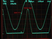
PS Here's a scope trace of a 5842 swinging a power tube grid 300V peak-peak
Attachments
Last edited:
Gee !
Which B+ value ?
About 190V/10mA
My signal generator may be pushing the 5842 grid about 0.5V positive, which seems to happen without an abrupt transition... It would be about 250V Pk-Pk if you kept the grid from going +
Oh yes, diode bias and a gyrator in the anode circuit
Attachments
Last edited:
Did you learn the causes of your blurred soundstage or early clipping ?
Both, unsolved mysteries! I will make a break and after that I will try to find why the early clipping . Then I will put everything on a breadboard and start from scratch with another first stage configuration. If I cannot find the cause. I will let you know!
Cheers,
Jean-Paul
OT: Mike, I'm using tube based gyrators as loads in my phono stage - nice to see someone else also using gyrators. I'm sure the fets work better, but I am getting good results..
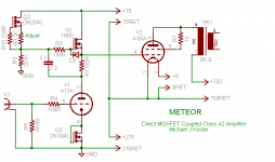
Note that Mike's circuit is not as obvious as it first seems due to the direct coupling and a floating 75V supply on top of the 270V supply.. The biasing arrangement for the 4-65 appears to be quite interesting. (And clever)
Note that Mike's circuit is not as obvious as it first seems due to the direct coupling and a floating 75V supply on top of the 270V supply.. The biasing arrangement for the 4-65 appears to be quite interesting. (And clever)
Last edited:
Did you learn the causes of your blurred soundstage or early clipping ?
NEWS!!!
I reached easily 7 W before clipping at the output when loading with 16 Ohms resistor instead of 8!
The first stage is working fine since I can reach 190 V p-p for 2.2V RMS signal before cliping at this stage but I am clipping at the output of the second stage of course (B+ is 180V on the 5842 for 22mA).
Do you think there is something wrong with the cabling of the output transformer?
Many thanks,
Jean-Paul
What is yor OPT? Whar is it's primary impedance? I bet that has something to do with it. Using the 16R taps effectively lower the output impedance, increase power and increase distortion (if I have that right). That would make it easier to drive inefficient speakers, but the low efficiency speaker itself, if an 8R load, shouldn't be the problem except that you can't get the sound volume you need. Maybe you OPT is poorly matched to your amp and speakers.
Can someone briefly overview what a gyrator does in a circuit?
I was just sold two pieces of crap as transformers at a famous 'Audiohile' shop in Paris at this time!......
I am now using the 4 Ohms wiring arrangement and I can reach 6 W with a better soundstage. I shoud not say crap because the sound is good but I am sure that they are not what they were supposed to be I mean Partridge TK 4519 with 2.3K primary. As recommended by many kind people here, I made some changes. I added grid stoppers on the 5842, placed the 280 ohms at the first stage of the PSU. I also omitted the last 100mF and replaced the 5R4 RCA with GZ34 (5AR4) Siemens wich gives about the same HT value at the end and could contribute also to the better soundstage?
PS: I know that someone here is making his own transformers which are better that all of the best ones on the market so if is OK to make a pair for me, I am ok to negociate the price!
Thanks to All,
Jean-Paul
Look at this link for how to measure your OPT.
Output Transformer Impedance
BudP makes O'Netics. He is on this site and I have heard nothing but good things about his transformers. His comments and advice is always respectful and very knowledgeable. He needs to be contacted directly to get his transformers. I tried this and did get a response, but somehow our communication broke down and I gave up. Probably my fault, a little persistence may be necessary because he is likely busy like everyone else.
There are a number of other well known and respected OPTs available at similar price ranges. Search the forum. I went with James, which some love and others think aren't quite good enough, although no one says they are not good.
If you measure yours as per that article, you may be able to figure out how to get them to work right. It is ok to use different taps if you need to, it is just good to know what you are doing and why. Sound like that is what you are doing anyway, so it depends if it is worth $300-$500 for a new pair of OPTs.
Very interesting. I learn so much here. I will read in detail an examine mines!
Thanks.
Jean-Paul
I agree with Kevin, the issue is reduced resolution on the amp.
Check all voltages and currents.
Check all filament supplies (too low voltage com degrade sound), but there are some detais cannot forget to correct:
grid stoppers, as already said
the 0,22uF is too small for a 250k load
the signal in the 300B goes via the filament transformar. Check impedance for signal.
The 1Vrms limit is not acceptable, you need more headroom, even if it means reducing stanby current for the tubes.
Wes you are right. I am usually using them with a 50 W solid state amp. This is just to confirm the pb of sounstage I have with the tube amps. The PM610 are 92 dB! And and the level in the room can be pretty loud!Bis repetita :
Yours Harbeth HL-P3 (82.5 dB) speakers haven't enough SPL for SE of 7 Watt.
Please try with minimum 92 dB speakers.
Philippe
Cheers,
Jean-Paul
TubeLab has no grid stopper resistors at the 5842 in his TubelabSE design. Are there any drawbacks using grid stoppers?
I use a Lundahl LL1623 as output transformer in my TubelabSE amplifier. The LL1623 is strapped for 6 kohm primary load impedance. The 300b runs att B+ 425 V 80mA and the 5842 at 180V 10 mA. I then get 8 W over 16 ohm before clipping. I really like the Lundahl OT, I think they sounds great
I use a Lundahl LL1623 as output transformer in my TubelabSE amplifier. The LL1623 is strapped for 6 kohm primary load impedance. The 300b runs att B+ 425 V 80mA and the 5842 at 180V 10 mA. I then get 8 W over 16 ohm before clipping. I really like the Lundahl OT, I think they sounds great
He has grid stoppers. R31 and R32. They are just absent from the schematic but you can see them in the parts list and the build instructions. In fact, he recommends increasing their size from the specified 1k to 4.7k and even using carbon comp. Apparently some people were having issues with oscillation.
TubeLab has no grid stopper resistors at the 5842 in his TubelabSE design. Are there any drawbacks using grid stoppers?
I have added gridstoppers as suggested by people in this forum but I can afirm that this did not change anything (in my case)! This is possible one of the 'principles of precaution' we often apply knowing that it cannot been worth with anyway. The same for the dampers I made for the drivers with some plumbers teflon tape and a metalic ring for curtains. I did'nt notice any microphonic effect before nor after fortunately!
- Status
- This old topic is closed. If you want to reopen this topic, contact a moderator using the "Report Post" button.
- Home
- Amplifiers
- Tubes / Valves
- Poor soundstage with SET 300B