MJL21193 said:
Hi Nico,
Looking good! You work fast!
Looks like a nice , compact board. I would like the Gerber's, if you don't mind. I would be making my own board for this, and might end up building a couple.
Once again, a beautiful job.
Hi John. Thanks for the compliment. The file is to big to post here, I will e-mail it to you (and anyone else who wants it)
Kind regards
Nico
The question that may be asked next is what does it sound like? Being the "designer" it is difficult to describe how a product performs sonically.
All I can say is that I have achieved every objective that I specified of which the most important for me was to be able to distinguish the different character of similar instruments. This means that the amp must be capable of faithfully producing the signal it receives.
My design motto has always been and remains: "Listening to Reality"
Now one must also keep in mind that I designed the amp around what I had: A pair of Senn HD650 and HD 595. Whether you would experience what I do with different phones I cannot tell.
I am very pleased with what I hear and I think the majority of people that knows what music sounds like in real life will have the same appreciation for this simple design.
Thanks to you all for putting up with my presence here on the forum, kindest regards to you all and may those of you who celebrate this festive season have a smashing time.
Nico
Stereoversion?
Hello Nico Ras
I have just ordered a pair of Sennheiser HD650, searched here and found this thread")
I looked at your homepage and found this project but I wonder about the picture on the board in the "RAS HP1 C-0060-502-R04" papers and also in your #37 post here.
It doesn't compare very well with the PCB layout that follows the project. Can you please explain whats in this mystery?
Hello Nico Ras
I have just ordered a pair of Sennheiser HD650, searched here and found this thread
I looked at your homepage and found this project but I wonder about the picture on the board in the "RAS HP1 C-0060-502-R04" papers and also in your #37 post here.
It doesn't compare very well with the PCB layout that follows the project. Can you please explain whats in this mystery?
Hi Radioman62,
this amp has gone through seven revisions already with different layout for different purposes. The circuit has been unchanged since I have had several favorable reports regarding the performance.
In my web site I tried to present a layout that would suit the general DIY'er not a particular extrusion like my own.
If you would like Gerbers of the one you see here I will gladly e-mail then to you.
Send me an e-mail and they are yours nico_ras@digisec.co.za
Kindest regards
Nico
Radioman62 said:
Yes Radioman62 I got it, I am very sorry for the delay but have been quite busy at work. I will send you the files in the next day or so. However, the stereo version is double sided. If this is a problem then I will see if I can make it single sided. I am lazy to route difficult layouts that is why I use double sided.
Kindest regards
Nico
Ok I'm not lazy but very Stingy I like to etch singlesided allthough some jumpers are Ok I think.
I have tools to do nice through holes and solder some component on the other side but not to many. It becomes a to cumbersome handcraft then.
Take your time Nico. I'm not in a hurry. I'll take what you have but I will not send gerbers to a commercial PCB factory. Then I rather do the artwork from scratch with Eagle.
I like to etch singlesided allthough some jumpers are Ok I think.I have tools to do nice through holes and solder some component on the other side but not to many. It becomes a to cumbersome handcraft then.
Take your time Nico. I'm not in a hurry. I'll take what you have but I will not send gerbers to a commercial PCB factory. Then I rather do the artwork from scratch with Eagle.
Radioman62 said:Ok I'm not lazy but very Stingy
I have tools to do nice through holes and solder some component on the other side but not to many. It becomes a to cumbersome handcraft then.
Take your time Nico. I'm not in a hurry. I'll take what you have but I will not send gerbers to a commercial PCB factory. Then I rather do the artwork from scratch with Eagle.
Check your e-mail, I just wrote you.
Regards
Nico
Nico is very kind and friendly
Me and Nico have had a nice conversation offline and he has done a PCB layout just for me. Very very generous
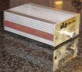
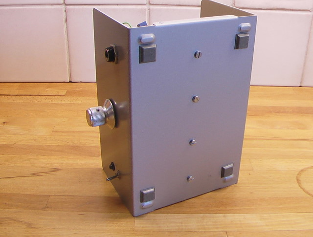
A single side mono version where the BD139's is attached on the solderside with their metalcase in such way that you should mount the card on the bottom of your box, or on the sides. The box could be the heatzink (Se pictures further down this post.)
This is the more basic design without the current mirror in the first post. It uses a single supply of 12 V with a virtual earth. Both 32 ohm and 300 ohm phones could be driven.
Nico's Class A rev.7 with virtual earth
I have done some small changes from the schematic.
For 2SC2240 and 2SA970 I use 2SC2632 and 2SA1124. The last two have the data 120V, 0,1A, 0,3W, 100Mhz
For MPSA06 and MPSA56 I use BC639 and BC640.
I didn’t have any 12pF miller caps so I use 10pF. Amp is stable anyway.
I have upped the LTP current a tad. I use 5.6k for R5 and 2.7k for R1.
There was some huge space on the card for C19 and C20 so I upped the lyth's to 4700uF Elna's
I have also put C17 back as decoupling for the current source as of the schematic on the first post in this thread.
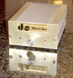
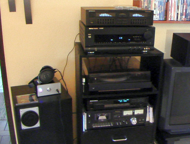
I have done a fast job with a cheapy, but enough, box for a first attempt to make myself a "Reference 1 unit".
Here are some pictures to cheer this text mass up a bit
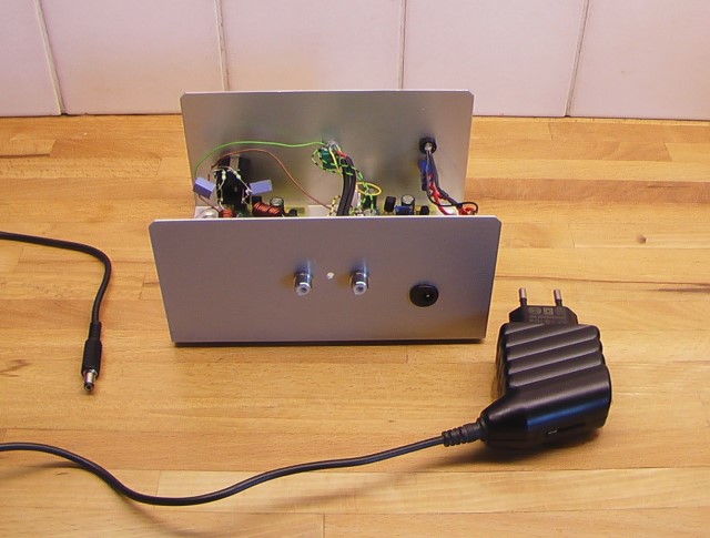
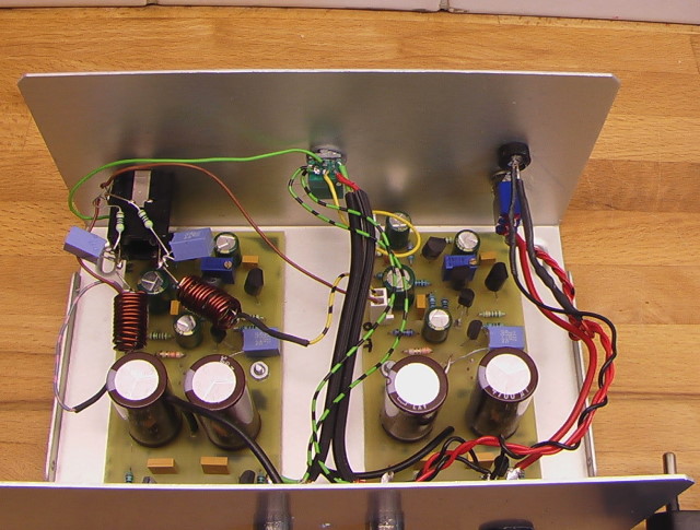
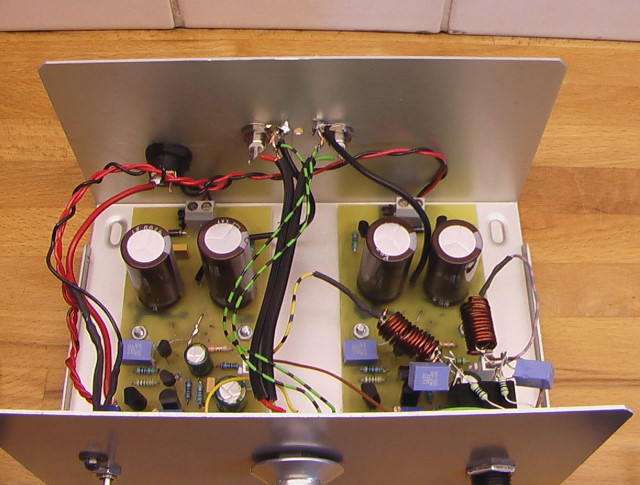
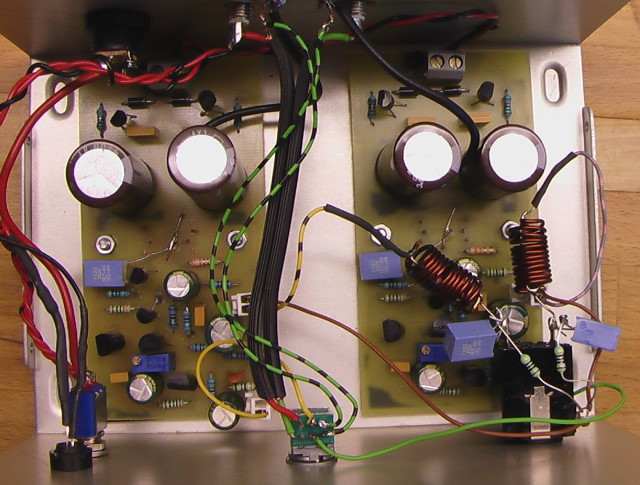
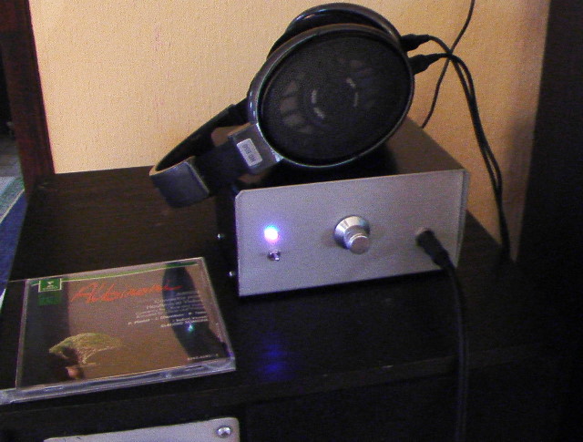
The output coil is a DIY coil measured 1.4uH, parallelled with 3.9ohm. The zobel is 470 ohm in serial with 100nF.
The volume knob was in the "knob box" and the volumepot is from a slaughtered carradio (An ALPS pot)
Me and Nico have had a nice conversation offline and he has done a PCB layout just for me. Very very generous
A single side mono version where the BD139's is attached on the solderside with their metalcase in such way that you should mount the card on the bottom of your box, or on the sides. The box could be the heatzink
(Se pictures further down this post.)This is the more basic design without the current mirror in the first post. It uses a single supply of 12 V with a virtual earth. Both 32 ohm and 300 ohm phones could be driven.
Nico's Class A rev.7 with virtual earth
I have done some small changes from the schematic.
For 2SC2240 and 2SA970 I use 2SC2632 and 2SA1124. The last two have the data 120V, 0,1A, 0,3W, 100Mhz
For MPSA06 and MPSA56 I use BC639 and BC640.
I didn’t have any 12pF miller caps so I use 10pF. Amp is stable anyway.
I have upped the LTP current a tad. I use 5.6k for R5 and 2.7k for R1.
There was some huge space on the card for C19 and C20 so I upped the lyth's to 4700uF Elna's
I have also put C17 back as decoupling for the current source as of the schematic on the first post in this thread.
I have done a fast job with a cheapy, but enough, box for a first attempt to make myself a "Reference 1 unit".
Here are some pictures to cheer this text mass up a bit
The output coil is a DIY coil measured 1.4uH, parallelled with 3.9ohm. The zobel is 470 ohm in serial with 100nF.
The volume knob was in the "knob box" and the volumepot is from a slaughtered carradio (An ALPS pot)
So how does this magnificent basic single ended Class A sound?
At first I thought I was in heaven These new headphones and this little amp strucked me big time.
But it wasn't all that religious when I found what sounded so bad with my ordinary AVR300 and phones.
I had a cheap source switcher to be able to switch in all kinds of video, phono, eq's and other stuff to be able to listen to both speakers through the HK amp and this new Class A love.
But when all was arranged for some practical listening sessions the magic was gone.
Thanks to that I found it was this outside switcher. It has gone to another place now
It's still more clean and liquid then my poweramp but not that big difference as I first thought. It did bring something good to it at the end. I have been more sensitive to errors now
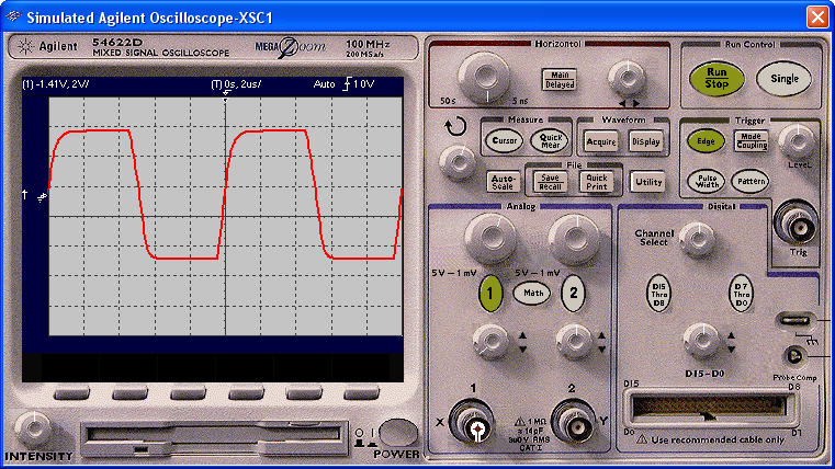
I have looked at the scope in the real world but not tested it with my 24bit192kHz M-Audio DAC on the computer yet. It will come soon I hope. Lack of time for all projects is the only enemy.
In the simulator (Multisim 10) I have done some measuring though.
3Volt rpm out with 300 ohm load is about 0.045% THD up to 20khhz. At -0.2 dB 100kHz there is 0.1% THD.
The -3dB point (~2.15 VAC RPM) is at 420kHz and gives 1% THD.
Squarevawe at 100kHz looks about the same as in the real world on my old Tectronix 912.
At first I thought I was in heaven
These new headphones and this little amp strucked me big time.But it wasn't all that religious when I found what sounded so bad with my ordinary AVR300 and phones.
I had a cheap source switcher to be able to switch in all kinds of video, phono, eq's and other stuff to be able to listen to both speakers through the HK amp and this new Class A love.
But when all was arranged for some practical listening sessions the magic was gone.
Thanks to that I found it was this outside switcher. It has gone to another place now
It's still more clean and liquid then my poweramp but not that big difference as I first thought. It did bring something good to it at the end. I have been more sensitive to errors now
I have looked at the scope in the real world but not tested it with my 24bit192kHz M-Audio DAC on the computer yet. It will come soon I hope. Lack of time for all projects is the only enemy.
In the simulator (Multisim 10) I have done some measuring though.
3Volt rpm out with 300 ohm load is about 0.045% THD up to 20khhz. At -0.2 dB 100kHz there is 0.1% THD.
The -3dB point (~2.15 VAC RPM) is at 420kHz and gives 1% THD.
Squarevawe at 100kHz looks about the same as in the real world on my old Tectronix 912.
One more thing with this amp.
It's completely dead silent when there is no signal fed to it. Several times these hectic building days when I've been testing it, I thought it was broken.
If I listen to CD and prepare with pretty high volume there is no noise at all .... then the music bombard you and you have to lower the volume.
I gave wrong numbers from the simulator. The THD values above was with the miller cap and feedbackcap at 47pF. I actually have just 10pF so the THD at 100khz is the same as 10khz in the simulator, around 0.044% ! I get the minus 1dB at 260kHz and 0.1% THD !
I will test the -3dB powerbandwith live and also do some RMAA software/PC cardstest. The live THD figures would be great fun to measure.
I will also change the decoupling caps I used. It's nothing I can hear but I have measured them with my new hefty LCR meter and they are not the best ones. Higher inductance and losses if I compare with others I have at hand. I'll change it so that I can sleep well and get that trifle out of my system
As for the schematic I will not change it. I have just used other transistors because I couldn't get Nico's variant easy. I don't think it does that much. The only change is the two resistor values around the diffamp. I just had to test slightly better slewrate and also, I don't like when transistors starve current, under 1mA each.
From the beginning I had to small resistor in the zobel (only 10 ohm instead of 470, which I have now) I got ugly unsymetric squarewaves at 10kHz with that low value. Maybe I sneaked at a poweramps zobel
Here you have the hole project as I got it from Nico. Just plot in my values I mention above and test them if you like. I don't think you can hear any difference between my slightly changed values and Nicos original version to me.
I hope to bring up a new interrest corner on my allready crowded hobby homepages soon I think. About this recently exploded DIY Hifi Hobby. I have been working and twekaing amps like a maniac day and night lately.
Now I'm also working on modifications to an old Marantz Cd player CD65II, but thats another story. Maybe in another thread or at my homepage later this spring.
- Status
- This old topic is closed. If you want to reopen this topic, contact a moderator using the "Report Post" button.
- Home
- Amplifiers
- Headphone Systems
- Please simulate my headphone amp