Now I am getting somewhere. Use the RF spectrum analyser in 10Hz bandwidth. At 1 Mhz, the 2nd harmonic is 51 dB down.
At 100kHz the 2nd harmonic is 106 dB down and the third harmonic just a little bump above the noise floor. I am happy, thanks to all for your comments.
I think I have a nice little headphone amp here, it sounds fantastic as well.
The MicroCAP9 demo package that I am playing with actually shows figures an order of magnitude better than real world measurments, which makes it a useful tool but not absolutely realistic.
Thanks for your comments P-A")
At 100kHz the 2nd harmonic is 106 dB down and the third harmonic just a little bump above the noise floor. I am happy, thanks to all for your comments.
I think I have a nice little headphone amp here, it sounds fantastic as well.
The MicroCAP9 demo package that I am playing with actually shows figures an order of magnitude better than real world measurments, which makes it a useful tool but not absolutely realistic.
Thanks for your comments P-A
Nico Ras said:
at only $ 4630, it is a steal.
Most consider that expensive, but if you're serious about this hobby or it you have commercial aspirations and you spend enough time using it, it's money well spent.
Nico Ras said:
It would appear as if c3 = 15p is optimal and 100pF causes slew limiting. With 15p I get about 20V/uS
Hi Nico,
I didn't see a big decrease in slew rate for that change. I did see better stability through the VAS.
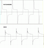
Below, I've attached a shot of an amp I'm working on. This is the output from the LTP with a square wave input at 20KHz. Beneath that is this headphone amp design , with the 15p Miller.
I'm no expert (heck, half the time I don't know what I'm doing), but I have simmed quite a few amps and the better ones show good stability here. I don't know that it makes even a slight difference to the final outcome. I do know that it has no effect on the distortion readings in the sim.
Attachments
don't know if it was a typo, but did you say you were testing distortion at 200Khz? or maybe you meant 200hz, 2khz, or 20khz......
because of the limited bandwidth of most diff amps, you won't have any negative feedback at 200khz, and so your distortion will be astronomical.....
because of the limited bandwidth of most diff amps, you won't have any negative feedback at 200khz, and so your distortion will be astronomical.....
unclejed613 said:don't know if it was a typo, but did you say you were testing distortion at 200Khz? or maybe you meant 200hz, 2khz, or 20khz......
because of the limited bandwidth of most diff amps, you won't have any negative feedback at 200khz, and so your distortion will be astronomical.....
You read right 200 kHz. This is not an op amp.
Ciao
MJL21193 said:
Most consider that expensive, but if you're serious about this hobby or it you have commercial aspirations and you spend enough time using it, it's money well spent.
Hi Nico,
I didn't see a big decrease in slew rate for that change. I did see better stability through the VAS.
Below, I've attached a shot of an amp I'm working on. This is the output from the LTP with a square wave input at 20KHz. Beneath that is this headphone amp design , with the 15p Miller.
I'm no expert (heck, half the time I don't know what I'm doing), but I have simmed quite a few amps and the better ones show good stability here. I don't know that it makes even a slight difference to the final outcome. I do know that it has no effect on the distortion readings in the sim.
unclejed613 said:don't know if it was a typo, but did you say you were testing distortion at 200Khz? or maybe you meant 200hz, 2khz, or 20khz......
because of the limited bandwidth of most diff amps, you won't have any negative feedback at 200khz, and so your distortion will be astronomical.....
Hi John,
I use silver mica cap for Miller and NFB, it does not have the ringing on the oscilloscope trace as indicated in the graph.
I must say the little amp sounds astonishing. I have been experimenting with several discreet topologies and found in general the wider the bandwidth the "cleaner" the sound.
Wide bandwidth improves linearity and reduces IM in other words mixing products of multiple frequencies. This is also some times referred to as colouring. A complex stimulus can produce many higher and sub order mixing products that produces "unfaithful" reproduction.
My primary objective is that of discriminate between the tonal characteristics of similar instruments. It has taken many years of experimentation but I am slowly achieving my objective.
unclejed613 said:don't know if it was a typo, but did you say you were testing distortion at 200Khz? or maybe you meant 200hz, 2khz, or 20khz......
because of the limited bandwidth of most diff amps, you won't have any negative feedback at 200khz, and so your distortion will be astronomical.....
Hi Unclejed613, When I was design engineer at HP we used discreet differential amps in most of our function generators linear output amplifiers stages operating well beyond 15MHz. I am not sure why you say that differential amps should not have NFB above 200 kHz.
Khron said:Just a quick question...
Isn't the Zobel network on the output supposed to be connected between OUT and GND? (it's connected between OUT and V- right now, in the schematic in the first post)
Sorry, yes it is to ground, slip of the mouse.
Nico Ras said:
I must say the little amp sounds astonishing. I have been experimenting with several discreet topologies and found in general the wider the bandwidth the "cleaner" the sound.
I believe it! I think I will put one together to hear for myself. Thanks.
Hi UncleJed,
just fooling around a little, it is possible to produce very linear amps.
This one is good for about 2MHz with THD at 1MHz <.001%. Phase linearity is <6 degrees DC - 2 MHz. Amplitude linearity is better than 0.025 dB from DC to 1MHz.
I have some HP transistors with FT=2GHz, that I kept for a really super amp one day. Maybe it is time that I get stuck into it.
The only problem with making super linear amps is that layout becomes critical.
Kind regards
Nico
Attachments
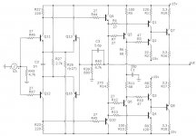
Hi Nico, I'm working on something similar right now, but using a National LME opamp for the front end, and a MOSFET output. Have you tried different current sinks on the output? I'm debating the merits of various designs- something like yours, or just putting a stable 431 regulated voltage on the gate of a MOSFET, or using the 431 for feedback off the sense resistor per the TI app note, or using an opamp to monitor and feed back off the sense resistor. Right now my simple "voltage on a FET" method is good for about 0.3% current change during operation (simulated). Do you have any thoughts as to how good the current sink needs to be, and what method might cause the least degradation? Also, what's the thinking behind your C16?
edit- I like your last posted design. I've made bad sounding amps with a Cdom cap, and try to stay with C across the feedback if at all possible, just as you've done. IMO, if the distortion of all types is low enough, it doesn't matter, but I don't always achieve that ;-)
edit- I like your last posted design. I've made bad sounding amps with a Cdom cap, and try to stay with C across the feedback if at all possible, just as you've done. IMO, if the distortion of all types is low enough, it doesn't matter, but I don't always achieve that ;-)
Conrad Hoffman said:Hi Nico, I'm working on something similar right now, but using a National LME opamp for the front end, and a MOSFET output. Have you tried different current sinks on the output? I'm debating the merits of various designs- something like yours, or just putting a stable 431 regulated voltage on the gate of a MOSFET, or using the 431 for feedback off the sense resistor per the TI app note, or using an opamp to monitor and feed back off the sense resistor. Right now my simple "voltage on a FET" method is good for about 0.3% current change during operation (simulated). Do you have any thoughts as to how good the current sink needs to be, and what method might cause the least degradation? Also, what's the thinking behind your C16?
edit- I like your last posted design. I've made bad sounding amps with a Cdom cap, and try to stay with C across the feedback if at all possible, just as you've done. IMO, if the distortion of all types is low enough, it doesn't matter, but I don't always achieve that ;-)
Hi Conrad
One of our esteemed members Gordy, referenced this paper by Walter Jung in a previous thread :
http://www.audioxpress.com/magsdirx/ax/addenda/media/jung2778.pdf
I have used and seen several other enthusiasts usings the LM317 as current source or sink (depending on your output arrangement) quite effectively.
Kind regards
Khron said:Given that there's a diff pair at the input, this headphone amp could be made to work with a balanced input, right?
I have never used balance input or thought of it, but I guess your right.
Good Jung reference and I found part II for higher current circuits and read that as well. After simulating a bunch of current sink circuits, yours has the fewest problems in terms of voltage overhead, stability, and regulation, so I'm going to steal it for my design ;-) I measured the impedance of my two mid-fi sets of headphones; one is about 50 ohms (Sony) and the other is about 250 ohms (ancient Koss Pro4AA), and a lot more reactive. The reactance for both is inductive at all frequencies (I think), and I haven't found a need for any output network at all on my amp. At least not during simulation. Now I just have to build something with real parts.
Conrad Hoffman said:Good Jung reference and I found part II for higher current circuits and read that as well. After simulating a bunch of current sink circuits, yours has the fewest problems in terms of voltage overhead, stability, and regulation, so I'm going to steal it for my design ;-) I measured the impedance of my two mid-fi sets of headphones; one is about 50 ohms (Sony) and the other is about 250 ohms (ancient Koss Pro4AA), and a lot more reactive. The reactance for both is inductive at all frequencies (I think), and I haven't found a need for any output network at all on my amp. At least not during simulation. Now I just have to build something with real parts.
Hi Conrad,
Thanks, you are welcome. There is nothing special about it, it has probably been done many times here by members of the forum as well.
I believe if I put something on the form it is in the public domain and for use by anyone whithout question.
Kind regards

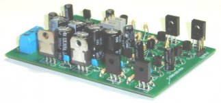
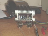
Nico Ras said:If anyone is interested I will post the PCB Gerber plots.
Hi Nico,
Looking good! You work fast!
Looks like a nice , compact board. I would like the Gerber's, if you don't mind. I would be making my own board for this, and might end up building a couple.
Once again, a beautiful job.
- Status
- This old topic is closed. If you want to reopen this topic, contact a moderator using the "Report Post" button.
- Home
- Amplifiers
- Headphone Systems
- Please simulate my headphone amp