I also have available a transformer with 0-600-700-800-900-1000V (1A).
My idea is to build a SEP that GM70 with work possibly under 1000V.
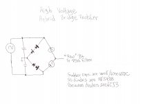
Thomas already gave you the answer to use this piece of "iron". Employ a hybrid 4 diode bridge. Two sets of series wired UF5408s form the bridge's ground legs. A pair of 6CJ3s form the "hot" legs.
On the transformers is also spelled "INTERMITTENT DUTY" (?) Do not know what it means, electronically speaking.
The best info. I know of regarding continuous and intermittent service comes from Hammond regarding their 700 series power trafos. Unfortunately, Hammond's web site seems to be down. When the site comes back, you will notice that CCS, AKA 24/7, ratings are lower. I suspect that I2R heating is the significant factor.
Hi Heli,
I am a neophyte: I need a schematic drawn.
I can not follow you completely due to lack of expertise in electronics and for the language.
I could not really understand what it means to the writing on the transformer "intermittent duty" Perhaps they are not suitable to provide tension so contimuativo. So would imutilizzabili for the purpose.
Hammond 700 Series transformers.
Notice that CCS (continuous commercial service) is rated lower than ICS (intermittent commercial service). Heat build up is the enemy of all things electronic. Dereate those intermittent service marked trafos by 35% and you should be on safe ground.
Notice that CCS (continuous commercial service) is rated lower than ICS (intermittent commercial service). Heat build up is the enemy of all things electronic. Dereate those intermittent service marked trafos by 35% and you should be on safe ground.
Attachments
Two more questions:
- On the side of the silicon diodes going to ground you need a switch to start the high voltage after one minute preheating valve 6Cj3?
- After the valves 6Cj3 the first capacitor value should it have? Okay a small capacitor (1uF) or is it better to abound (20uF or more)?
Thanks
- On the side of the silicon diodes going to ground you need a switch to start the high voltage after one minute preheating valve 6Cj3?
- After the valves 6Cj3 the first capacitor value should it have? Okay a small capacitor (1uF) or is it better to abound (20uF or more)?
Thanks
Hi!
No
This depends on the filter chain you have in mind (LC, LCLC or other) and the ripple figure you are shooting for. Keep the cap value as small as possible. Best to simulate the PSU with PSUD and check that peak currents are within limits.
Since you wrote that you are a neophyte: Please be careful. Your questions show that you have little experience with such PSUs. Such voltages are dangerous and special care is needed. Make sure all parts used have proper voltage ratings. Especially also the heater transformer for the 6CJ3. In case of doubt consult somebody to help and review your work before you power it up
best regards
Thomas
- On the side of the silicon diodes going to ground you need a switch to start the high voltage after one minute preheating valve 6Cj3?
No
- After the valves 6Cj3 the first capacitor value should it have? Okay a small capacitor (1uF) or is it better to abound (20uF or more)?
This depends on the filter chain you have in mind (LC, LCLC or other) and the ripple figure you are shooting for. Keep the cap value as small as possible. Best to simulate the PSU with PSUD and check that peak currents are within limits.
Since you wrote that you are a neophyte: Please be careful. Your questions show that you have little experience with such PSUs. Such voltages are dangerous and special care is needed. Make sure all parts used have proper voltage ratings. Especially also the heater transformer for the 6CJ3. In case of doubt consult somebody to help and review your work before you power it up
best regards
Thomas
Hi Thomas,
Even if you are a beginner I have already made some tube amp. When I make sure I have worked out a scheme to build the amp from a friend who has solid experience.
I am not even able to make a weld, but I have friends who have already built for them with amplifiers 211, 845 and more.
I have discarded the idea of using transformers INTERMITTENT DUTY as several audiophile friends are of the opinion that can not be used in continuous service.
I will use the transformer 0-600-700-800-900-1000V (1A) beginning to make it work first and then go over to 600V (I think not more than 800V).
The filter that I'm going to use consists of 1 to 1 uF capacitor ICAR SP25 (1500V) or even 2 to get 0,5uF (3000V). After the small capacitor I have two chokes from 5H (400mA). These could follow the capacitor ICAR put on a positive branch and the other on the negative branch of the filter (crossed) or one behind the other (CLCL): the capacitors to follow are of MKP from 22uF (1400V). Alternatively, I also have 75uF (1400V).
ERRATA CORRIGE_
Even if I are a beginner I have already made some tube amp. When I make sure I have worked out a scheme to build the amp from a friend who has solid experience.
(jokes of the automatic translator)
Today I found in the cellar 2 huge capacitor ICAR SP25 4000Vlcc. Perhaps even only one of these could be used as the first capacitor after the tubes 6JC3.
Another doubt. The scheme suggested by Eli how much current it can handle? 700 mA???
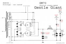
My idea is to build a final single ended parallel GM70. As a driver I have a couple of EC8020 jealously guarded for years for something important.
A final of this type (four tubes GM70 + Two EC8020) you eat 500-600mA easily (at least) ...
Even if I are a beginner I have already made some tube amp. When I make sure I have worked out a scheme to build the amp from a friend who has solid experience.
(jokes of the automatic translator)
Today I found in the cellar 2 huge capacitor ICAR SP25 4000Vlcc. Perhaps even only one of these could be used as the first capacitor after the tubes 6JC3.
Another doubt. The scheme suggested by Eli how much current it can handle? 700 mA???
My idea is to build a final single ended parallel GM70. As a driver I have a couple of EC8020 jealously guarded for years for something important.
A final of this type (four tubes GM70 + Two EC8020) you eat 500-600mA easily (at least) ...
Hi!
You should work out the details first before designing the PSU. Calculate the total current needed including all stages and bleeder resistors. Then design the PSU accordingly with some overhead. And then select the right parts. 700mA would be pushing it for both the 6CJ3 and power transformer.
Please do yourself a favour and use the EC8020 for something they are better suited for. I love the EC8020, but not as a driver for such large tubes. They would not have a lot of headroom. I know it is fashionable to use such tubes and be able to stick with two stages. But simpler is not always better.
Use the EC8020s to build a top notch phono stage and don't waste them as drivers in a power amp.
Best regards
Thomas
Last edited:
Hi Thomas,
These days I tried to understand the meaning of the term "headroom". To no avail. Then I found the solution to the riddle here:
VinylSavor: Gain, Headroom and Power
From what I was able to understand (automatic translator is sometimes terrible) it is useless to think about replacing the tube EC8020 with other tubes as similar. EC8010, D3a, 12GN7, E55L, E810, etc.
The GM70 works sometimes also around the -100V. Therefore requires a driver capable of 200Vpp. For a good "headroom" 400Vpp or more. The EC8020 with a working point of 285 V to plaque, - 4.4 V grid, current 28 mA, is capable of a swing of about 400 Vpp (just enough).
To have a "headroom" powerful I understand that the family of tubes Compactron 6HS5-6HV5A is the obvious choice. Perhaps WE416B WE416C and would make a good job, but their implementation is complex and problematic.
I would like to know from Thomas if my thinking is right. And if there are other tubes alternative and easier to use.
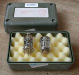
I forgot: I bought the tubes 6CJ3 and I would like to start doing some experiment with them. I would like to know whether to make the bridge hybrid silicon diodes and 2 tubes 6CJ3 designed for me by Eli can tie together the strands of the 2 valves only secondary to 6.3V (4-5A) or do I need to tie on 2 secondary separated.
Thanks
Thanks
Hi,
HIPOT is a rating standard. It stands for High Potential meaning that it is built to be used with high voltages and currents.
IOW, it has sufficient insulation so it will not break down under these working conditions nor exhibit high leakage current etc.
I suppose what Thomas meant is for you to use devices that meet sufficient safety standards.
Cheers,
Hi!
That would operate it right at it's limits. Something you don't want to do with this precious tube.
Yes. There are many possible tubes when you allow three stages or the use of an input transformer
Best regards
Thomas
The EC8020 with a working point of 285 V to plaque, - 4.4 V grid, current 28 mA, is capable of a swing of about 400 Vpp (just enough).
That would operate it right at it's limits. Something you don't want to do with this precious tube.
I would like to know from Thomas if my thinking is right. And if there are other tubes alternative and easier to use.
Yes. There are many possible tubes when you allow three stages or the use of an input transformer
Best regards
Thomas
Thank you all for the answers.
(for Thomas) It would be interesting to know something more about this topic. I really like amplifiers with input transformer. Even more I like the E55L tubes, which with a little resistance lower than the EC8020 and with a higher anode dissipation (10W) I hope they are suitable as a driver of GM70.
I enclose a rare photo showing EC8020 and E55L together in a pack demo reserved for companies sent by Telefunken. This picture shows that the two tubes are born together, and for similar applications. The EC8020 (very rare because it is produced in small numbers) was born only in Telefunken factory. While the E55L (easier to find still around) I think I was born just in Mullard factory, even if they are then rebranded by many brands.
Attachments
Hi Thomas & Eli,
with great difficulty I managed to find four sockets for 6Cj3. Waiting to find all the material needed to build the amp I drew a diagram provisional. The values of output voltage feeder and are presumed to be checked. Please take a look, because given my lack of experience may contain some errors. I did not deliberately designed to connect the cathodes of the filament 6CJ3: is it really necessary?
with great difficulty I managed to find four sockets for 6Cj3. Waiting to find all the material needed to build the amp I drew a diagram provisional. The values of output voltage feeder and are presumed to be checked. Please take a look, because given my lack of experience may contain some errors. I did not deliberately designed to connect the cathodes of the filament 6CJ3: is it really necessary?
Attachments
- Status
- This old topic is closed. If you want to reopen this topic, contact a moderator using the "Report Post" button.
- Home
- Amplifiers
- Tubes / Valves
- Please Help: 6CJ3 Damper Diode Tube as Rectifier Question